数字逻辑电路实验报告

学院:计算机科学与通信工程
专业:
姓名:
学号:
指导老师:
多功能数字钟
一、设计任务及要求
(1)拥有正常的时、分、秒计时功能。
(2)能利用实验板上的按键实现校时、校分及清零功能。
(3)能利用实验板上的扬声器做整点报时。
(4)闹钟功能
(5)在MAXPLUS II 中采用层次化设计方法进行设计。
(6)在完成全部电路设计后在实验板上下载,验证设计课题的正确性。
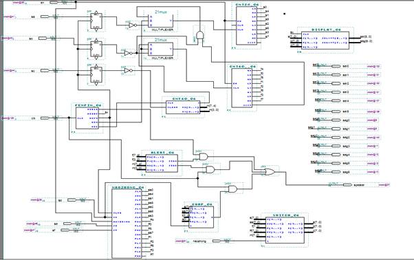
二、多功能数字钟的总体设计和顶层原理图
作为根据总体设计框图,可以将整个系统分为六个模块来实现,分别是计时模块、校时模块、整点报时模块、分频模块、动态显示模块及闹钟模块。
(1)计时模块
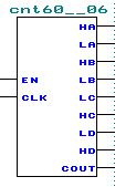
该模块使用74LS160构成的一个二十四进制和两个六十进制计数器级联,构成数字钟的基本框架。二十四进制计数器用于计时,六十进制计数器用于计分和秒。只要给秒计数器一个1HZ的时钟脉冲,则可以进行正常计时。分计数器以秒计数器的进位作为计数脉冲。
用两个74160连成24进制的计数器,原图及生成的器件如下:


用两个74160连成的60进制计数器,原图及生成的器件如下:


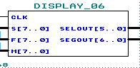
(2)校时模块
校时模块设计要求实现校时,校分以及清零功能。
*按下校时键,小时计数器迅速递增以调至所需要的小时位。
*按下校分键,分计数器迅速递增以调至所需要的分位。
*按下清零键,将秒计数器清零。
注意事项:① 在校分时,分计数器的计数不应对小时位产生影响,因而需要屏蔽此时分计数器的进位信号以防止小时计数器计数。
② 利用D触发器进行按键抖动的消除 ,因为D触发器是边沿触发,在除去时钟边沿到来前一瞬间之外的绝大部分时间都不接受输入,可以消除抖动。
③ 计时采用1HZ的脉冲驱动计数器计数,而校时则需要较高频率的信号驱动以达到快速校时的目的。因此这两种脉冲信号就需要两路选择器进行选择,条件即为是否按键。
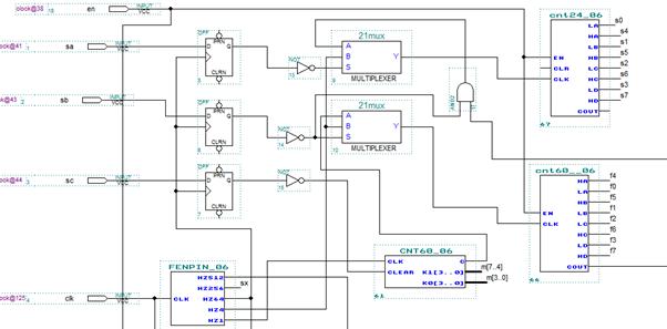
注:D触发器用于按键的消抖,接更高的频率用于校时和校分,二路选择器用于区分是正常计时还是校时。
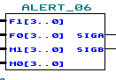
(3)整点报时模块
计时到59分50秒时,每两秒一次低音报时,整点时进行高音报时。以不同频率的脉冲信号区分低音和高音报时。报时的条件是计数器计数至所需要的时间点,因而需要一个比较模块,将分计数器和秒计数器的输出连至比较模块输入端完成比较过程。
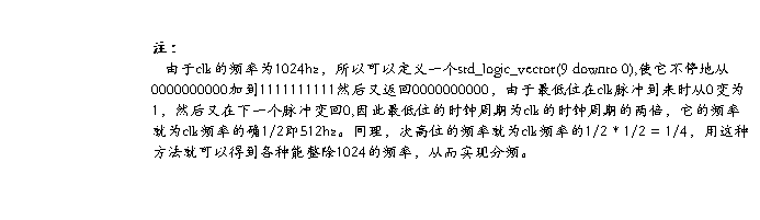
注:
F1表示计数器分的高位,F0表示分的低位;M1表示秒的高位,M0表示秒的低位。当时间为59分00,02,04,06,08进行低音报时,当为整点时进行高音报时。SIGA为1时低音报时,SIGB为1时高音报时。
(4)分频模块
在这个系统中需要很多种不同频率的脉冲信号,这些均可以通过一个基准频率分频器生成。分频器就是一个进制很大的计数器,利用计数器的分频功能,从不同的输出位得到所需要的脉冲信号。

(4)动态显示模块
在6个不同的时间段分别将每组时间经过七段译码后输出到6个数码管,当某一组时间的七段码到达时,只点亮对应位置上的数码管,显示相应的数字,6次一个循环,形成一个扫描序列。利用人眼的视觉暂留则可以同步显示6个数字。
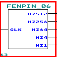
 注:
注:
CLK为时钟信号,S为计数器的小时,F为分,M为秒,SELOUT为六路选择器,选择哪个数码管工作,SEGOUT为七段译码器,使数码管显示数字。

(6)闹钟模块
注意事项:① 设定的闹钟的时间应使用新的计数器进行存储,与正常的计时互不干扰。
② 与正常计时状态的显示切换。可以设定一个按键,用于选择是将计时时间还是将闹钟时间送至动态显示模块。
③ 应实现一个比较模块,当计时到与闹钟时间相等时,则驱动扬声器鸣叫。
④ 闹钟响声应限定在一定时间内,且在这段时间内应随时可以通过按键取消闹时状态。
闹钟调时和分以及正常计时与闹钟定时之间的选择原图及生成的器件如下:

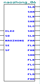
闹钟界面和正常计时界面的转换器件如下:
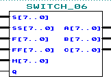 注:
注:
S表示计时器的时,F表示计时器的分,M表示计数器的秒;
SS表示闹钟的时,FF表示闹钟的分;Q为计时和闹钟两个界面的切换开关,ABC为输出的时间。
正常计时时间和设定闹钟时间的比较器件如下:
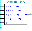
注:
S 表示正常计时的小时,F表示闹钟的分;
SS表示闹钟的小时,FF表示闹钟的分;Q为闹钟的开关,D当Q为1时,
并且正常计时的时间和闹钟时间 相等时输出为1,否则为0。
三、心得和体会
经过一个星期对数字时钟实践的制作,从中学到了很多。首先是对EDA的VHDL语言的更深层次认识,本来觉得EDA编程语言比较麻烦,可是接触了以后也就觉得它还是有它方便的地方,尤其是和图形编程结合的特点。其次,这个实践其实到目前为止应该还不是一个成功的作品,还是有很多的仿真没有完成,原因可能也是自己的技术不到位。但是整个制作的过程中,它促进了同学之间的相互沟通,也让我在自己的专业知识的学习过程中,更多的,更好的学习一门知识,用于以后的实践应用中,做这个数字钟的设计中包含了很多不同功能的程序,让我在其中学到了一些程序的中的思路,特别一步一步去把错误的程序改正确是一种很有成就感的事!这样让我学到了更多的知识!特别是在做数字时钟闹钟的那个模块时,我在网上查了好多程序,证实了好多错误的程序并从中更改出正确的程序!相信,现在只是一个起步,以后,我会更好的努力,学习,对EDA孰能生巧。
附录:
用VHDL语言写的六十进制计数器如下:
library ieee;
use ieee.std_logic_1164.all;
use ieee.std_logic_unsigned.all;
entity cnt60_06 is
port (clk:in std_logic;
clear:in std_logic;
c:out std_logic;
k1,k0:out std_logic_vector(3 downto 0));
end cnt60_06;
architecture cnt of cnt60_06 is
signal q1,q0:std_logic_vector(3 downto 0);
begin
process(clk,clear)
begin
if(clear='1')then
q1<="0000";q0<="0000";c<='0';
else
if(clk'event and clk='1')then
if(q1="0101" and q0="1001")then-----到59
q1<="0000";q0<="0000";c<='1';
elsif(q1<"0101" and q0="1001")then
q0<="0000";q1<=q1+'1';c<='0';
elsif(q0<"1001") then
q0<=q0+'1';
end if;
end if;
end if;
k1<=q1;
k0<=q0;
end process;
end cnt;
用VHDL语言写的报时器源代码如下:
library ieee;
use ieee.std_logic_1164.all;
use ieee.std_logic_unsigned.all;
entity alert_06 is
port(f1,f0,m1,m0:in std_logic_vector(3 downto 0);
siga,sigb:out std_logic);
end alert_06;
architecture a of alert_06 is
begin
siga<='1'when(f1="0101" and f0="1001" and m1="0101" and (m0="0000" or m0="0010" or m0="0100" or m0="0110" or m0="1000"))else'0';
sigb<='1'when(f1="0000" and f0="0000" and m1="0000" and m0="0000")else'0';
end a;
用VHDL语言写的分频器的源代码如下:
library ieee;
use ieee.std_logic_1164.all;
use ieee.std_logic_unsigned.all;
entity fenpin_06 is
port (clk:in std_logic;
hz512,hz256,hz64,hz4,hz1:out std_logic);
end fenpin_06 ;
architecture f of fenpin_06 is
signal cc: std_logic_vector(9 downto 0);
begin
process(clk)
begin
if(clk'event and clk='1') then
if(cc="1111111111")then
cc<="0000000000";
else
cc<=cc+1;
end if;
end if;
end process;
hz512<=cc(0);
hz256<=cc(1);
hz64<=cc(3);
hz4<=cc(7);
hz1<=cc(9);
end f;
用VHDL语言写的动态扫描的源代码如下:
library ieee;
use ieee.std_logic_1164.all;
use ieee.std_logic_arith.all;
use ieee.std_logic_unsigned.all;
entity display_06 is
port(clk:in std_logic;
s :in std_logic_vector(7 downto 0);
f :in std_logic_vector(7 downto 0);
m :in std_logic_vector(7 downto 0);
selout:out std_logic_vector(5 downto 0);
segout:out std_logic_vector(6 downto 0)
);
end display_06 ;
architecture a of display_06 is
signal number:std_logic_vector(3 downto 0);
signal sel :std_logic_vector(5 downto 0);
signal seg :std_logic_vector(6 downto 0);
signal q :std_logic_vector(2 downto 0);
begin
a:process(clk)
begin
if(clk'event and clk='1')then
q<=q+1;
end if;
end process a;
process(q)
begin
case q is
when"000"=>sel<="000001";
when"001"=>sel<="000010";
when"010"=>sel<="000100";
when"011"=>sel<="001000";
when"100"=>sel<="010000";
when"101"=>sel<="100000";
when others=>sel<="000000";
end case;
end process;
process
begin
if sel ="000001"then
number<=m(3 downto 0);
elsif sel="000010"then
number<=m(7 downto 4);
elsif sel="000100"then
number<=f(3 downto 0);
elsif sel="001000"then
number<=f(7 downto 4);
elsif sel="010000"then
number<=s(3 downto 0);
elsif sel="100000"then
number<=s(7 downto 4);
else
number<="1111";
end if;
end process;
process(number)
begin
case number is
when"0000"=>seg<="0111111";
when"0001"=>seg<="0000110";
when"0010"=>seg<="1011011";
when"0011"=>seg<="1001111";
when"0100"=>seg<="1100110";
when"0101"=>seg<="1101101";
when"0110"=>seg<="1111101";
when"0111"=>seg<="0000111";
when"1000"=>seg<="1111111";
when"1001"=>seg<="1101111";
when others=>seg<="0000000";
end case;
end process;
selout<=sel;
segout<=seg;
end a;
闹钟界面和正常计时界面之间的切换源代码如下:
library ieee;
use ieee.std_logic_1164.all;
use ieee.std_logic_unsigned.all;
entity switch_06 is
port(s:in std_logic_vector(7 downto 0);
ss:in std_logic_vector(7 downto 0);
f:in std_logic_vector(7 downto 0);
ff:in std_logic_vector(7 downto 0);
m:in std_logic_vector(7 downto 0);
Q:in std_logic;
A:out std_logic_vector(7 downto 0);
B:out std_logic_vector(7 downto 0);
C:out std_logic_vector(7 downto 0));
end switch_06;
architecture a of switch_06 is
begin
process(Q,s,ss,f,ff,m)
 Begin
Begin
if(Q='1') then
A<=ss;B<=ff;C<="00000000";
else
A<=s;B<=f;C<=m;
end if;
end process;
end a;
正常计时时间和设定的闹钟时间之间的比较的源代码如下:
library ieee;
use ieee.std_logic_1164.all;
use ieee.std_logic_unsigned.all;
entity comp_06 is port(
s,ss,f,ff:in std_logic_vector(7 downto 0);
d:out std_logic;
Q:in std_logic);
end comp_06;
architecture behavior of comp_06 is
begin
process(Q,s,ss,f,ff)
begin
if(rising_edge(Q))then
if(s=ss and f=ff)then
d<='1';
else d<='0';
end if;
end if;
end process;
end behavior;
-
数字逻辑电路课程设计实验报告
数字逻辑电路课程设计报告数字逻辑电路课程设计多功能数字时钟班级信息安全1002姓名潘祥熙学号3100604048指导老师袁晓云时间…
-
数字逻辑电路实验报告
数字逻辑电路实验报告电子72班07051042冯天宇1数字逻辑电路实验报告计数器设计与应用学院电信学院班级电子72班姓名冯天宇学号…
-
数字逻辑电路实验报告模板
数字逻辑电路实验报告第次实验姓名学号级系班邮箱时间正文由下面八项内容评定每次实验报告成绩一实验目的本次实验预期要学习到的知识方法等…
-
数字逻辑电路实验报告
数字逻辑电路设计多功能数字钟学院计算机科学与通信工程专业姓名学号指导老师江苏大学计算机10数字逻辑电路设计报告多功能数字钟一设计任…
-
哈工大 数字逻辑电路与系统实验报告
HarbinInstituteofTechnology数字逻辑电路与系统课程名称院系班级姓名学号教师哈尔滨工业大学20xx年12月…
-
大连海事大学数字逻辑电路课程设计实验总结报告
数字逻辑电路课程设计实验总结报告题目一:用J-K触发器设计13进制加法计数器一、设计过程:参见设计实验报告(真值表,卡诺图)。二、…
-
东南大学 数字电路实验 第4章_时序逻辑电路
东南大学电工电子实验中心实验报告课程名称数字逻辑电路设计实践第4次实验实验名称基本时序逻辑电路院系信息科学与工程学院专业信息工程姓…
-
数字电路实验二--译码器实验报告深圳大学--郭治民
深圳大学实验报告实验课程名称数字电路与逻辑设计实验项目名称学院计算机与软件学院专业计算机科学与技术报告人同组人指导教师实验时间实验…
-
数字电路实验报告3
暨南大学本科实验报告专用纸课程名称数字逻辑电路实验成绩评定实验项目名称三态门特性研究和典型应用指导教师实验项目编号08060038…
-
数字电路与数字逻辑大型实验报告
数字电路与数字逻辑大型实验报告1一实验内容一QuartusII操作练习1用原理图输入法设计一个3线8线译码器二数字频率计设计三倒计…