51单片机控制的遥控车制作过程总结和体会
我于2010/7/16日才正式决定做遥控车。到2010/7/31中午正式全部完成。
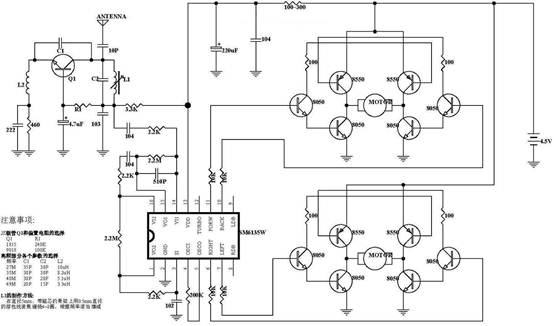
首先 我做的遥控车目前的功能有:前进,后退,开始,停止,加速,减速,左转,右转
用的无线发送接收方式,用pt2262编码,pt2272解码!
1, 测速模块(虽然最后没用上,还是说说),测速的方式有很多很多,我们选择的方式有红外测速,光敏测速。最后查完资料决定用光敏测速,我是在机械鼠标上拆的光敏三极管,通过计固定时间内的低电平次数,就可以测出转速,但是使用时出了问题,几乎三极管集电极电压保持在1.7伏左右,主要是因为受自然光影响,随后对其进行密封,只留个很小的进光孔,效果还不错
2, 电机驱动部分。网上流传甚广的是如下电路图
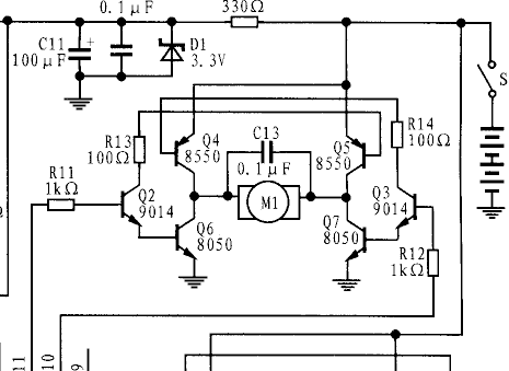
11脚出现高电平时,使左边的9014导通,从而左边的8050和右边的8550导通,经实验,确实没问题,但是如果第11和10同时为高呢?因为单片机通电的各引脚瞬间是高电平,将导致两边8550,8050没经过电机而导通。其二,我实验的时候,反正经常出现控制不了的状况,即让左边9014导通,而电机不能正常转动,其三,当电机整个驱动电压为7.6V时,9014门极控制为4.5V,发现电机转动的很慢,而流过电机的电流才0.4A
,而电机端电压居然高达十几伏,最后还不慎将整个电路烧毁了
最后我在网上找到了这个电路:
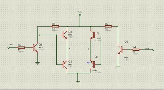
其中A,B点是接电机的。
这个电路就非常好,好在哪儿?
首先:两控制端同为低,或同为高,电机都不转,8050,8550均未全部导通,那么就不存在短路的情况,其二只有两个引脚一高一低的时候,电机才会正常运转。
而这个电路的驱动能力是相当的好,即使是4.5V的干电池都能轻而易举的让电机快转。但是当把控制端接到单片机上去之后,让单片机输出口输出“1”,而电机并未转动,IO口电压很低,最后我想到了可能是单片机的IO驱动能力不够,因为单片机的IO只能驱动八个TTL电路,最后我在电机控制的各引脚接了13K的上拉电阻(太大太小都不行),然后OK了,电机完全在控制之中了。
3:无线接收模块:
pt2262和pt2272—M4(瞬态型)的地址端设成一样之后,2262发号,2272接收,接收时VT会输出一个高脉冲,我将其接个非门,目的是能产生中断,因为后面我还打算把语音部分加上,当然你想简单点则可以不加,只是程序要稍作改动。未接单片机时,接收效果非常好,很远都能接收到,但是接上单片机之后发现,2272低电平为0V,高电平却为0.65V,网上说可能是单片机的端口设置成了输出,我检查了一遍,发现并不是这个问题。我想可能和2272的地址设置有关系,因为D0和A11为同一引脚,而单片机的各引脚初始状态为1,你把它改成0 也不对,数据端结果误认为成了地址控制了,所以我索性将各个2272(D0---D3)数据端口接个反相器74HC04;一下子,能够收号了,完全正确。
至此我的小车就做出来了,看着简单,做的时候才知道“锅儿是铁倒的,馍馍是面做的”。
发射部分程序:51单片机控制,因为后面准备做语音部分,所以用单片机发送,容易控制和实现半智能化;电路图看程序即可看出;
#include "reg51.h"
sbit start=P3^3;
sbit stop=P3^4;
sbit qianj=P1^2;
sbit hout=P1^1;
sbit zuoz=P1^0;
sbit youz=P1^3;
sbit jias=P3^1;
sbit jians=P3^2;
sbit fashe=P2^4;
void delay_ms(unsigned char nn)
{
unsigned char i,j,k;
for(i=nn;i>0;i++)
for(j=2;j>0;j--)
for(k=248;k>0;k--);
}
void main()
{
fashe=0;
while(1)
{
if(qianj==0)
{
delay_ms(10);
if(qianj==0)
{
while(!qianj);
P2=0x08;//前进
fashe=1;
delay_ms(50);
fashe=0;
}
}
if(hout==0)
{
delay_ms(10);
if(hout==0)
{
while(!hout);
P2=0x04;
fashe=1;
delay_ms(50);
fashe=0;
}
}
if(zuoz==0)
{
delay_ms(10);
if(zuoz==0)
{
P2=0x02;
fashe=1;
delay_ms(50);
fashe=0;
}
}
if(youz==0)
{
delay_ms(10);
if(youz==0)
{
P2=0x01;
fashe=1;
delay_ms(50);
fashe=0;
}
}
if(jias==0)
{
delay_ms(10);
if(jias==0)
{
P2=0x0c;
fashe=1;
delay_ms(50);
fashe=0;
}
}
if(jians==0)
{
delay_ms(10);
if(jians==0)
{
P2=0x03;
fashe=1;
delay_ms(50);
fashe=0;
}
}
if(start==0)
{
delay_ms(10);
if(start==0)
{
P2=0x0a;
fashe=1;
delay_ms(50);
fashe=0;
}
}
if(stop==0)
{
delay_ms(10);
if(stop==0)
{
P2=0x05;
fashe=1;
delay_ms(50);
fashe=0;
}
}
}
}
接收部分程序:
#include "reg52.h"
#include "intrins.h"
sbit zuo=P2^2;
sbit you=P2^3;
sbit qianj=P2^0;
sbit hout=P2^1;
sbit p32=P3^2;
unsigned char p_time=0;
unsigned char pwmh=200;
bit flag1=0; //收号标志
bit qh=0;
/*
void delay_ms(unsigned char nn)
{
unsigned char i,j,k;
for(i=nn;i>0;i++)
for(j=2;j>0;j--)
for(k=248;k>0;k--);
}
*/
void delay_us(unsigned char nn)
{
unsigned char m;
unsigned char n;
for(m=0;m<=nn;m++)
for(n=0;n<=33;n++)
;
}
void jiasu(void)
{
if(pwmh+5>100)
pwmh=100;
else pwmh+=5;
}
void jiansu(void)
{
if(pwmh<=30)
pwmh=30;
else pwmh-=5;
}
void zuoz(void)
{
zuo=1;you=0;
delay_us(30);
zuo=0;you=0;
}
void youz(void)
{
you=1;zuo=0;
delay_us(30);
you=0;zuo=0;
}
void start(void)
{
TR0=1;
pwmh=30;
qh=0;
}
void stop(void)
{
TR0=0;
pwmh=0;
}
int0()interrupt 0 using 1{
flag1=1;
}
timer0()interrupt 1 using 1{
p_time++;
if(qh==0)
{
if(p_time<=pwmh)
{qianj=1;hout=0;}
else {qianj=0;hout=0;}
}
if(qh==1)
{
if(p_time<=pwmh)
{hout=1;qianj=0;}
else {hout=0;qianj=0;}
}
if(p_time==255)
p_time=0;
}
void jieshou(void)
{
unsigned char js;
if(flag1==1)
{
flag1=0;
_nop_();
_nop_();
_nop_();
_nop_();
_nop_();
js=P2&0xf0;
switch(js)
{
case 0x00: break;
case 0xf0: break;
case 0xa0: jiasu(); break;
case 0x50: jiansu();break;
case 0x70: zuoz(); break;
case 0xd0: youz(); break;
case 0xe0: qh=0; break; //前后标志位为0,则表示前进
case 0xb0: qh=1; break; //前后标志位为1,则表示后退
case 0x60: start(); break;
case 0x90: stop(); break;
default: break;
}
}
}
void init()
{
TMOD=0x02; //只产生pwm
TH0=0x38;
TL0=0x38;
ET0=1;
EA=1;
EX0=1;
IT0=1;
}
void main()
{
init();
while(1)
{
jieshou();
}
}
第二篇:51单片机中断总结
51单片机中断总结:
1. 查询优先级为固定的(外部中断0>定时器0>外部中断1>定时器1>串行中断)。
2. 执行优先级可以通过IP寄存器进行设置(高/低)。
3. CPU同时收到多个中断请求时,首先响应优先级较高者,然后相应优先级较低者;如果优先级相同,则按照查询优先级顺序依次响应。
4. 正在执行的中断服务,不能被同级或更低级的中断请求打断,但会被更高级的中断请求打断。推论(1)高优先级的中断不能被任何其它中断所打断(2)低优先级的中断只能在没有任何中断服务运行时得到响应。
5. 对于定时器和外部中断,在进入中断服务后,其中断标志位会自动清零;对于串行中断,由于有两个中断源,需要手动查询并清零RI或/和TI。
if (RI) {
}
if (TI) {
}
6. 如果是使用汇编写中断服务,需要保护累加器、状态寄存器、寄存器组等
8051 Tutorial: Interrupts
/tutint.php
As the name implies, an interrupt is some event which interrupts normal program execution. As stated earlier, program flow is always sequential, being altered only by those instructions which expressly cause program flow to deviate in some way. However, interrupts give us a mechanism to "put on hold" the normal program flow, execute a subroutine, and then resume normal program flow as if we had never left it. This subroutine, called an interrupt handler, is only executed when a certain event (interrupt) occurs. The event may be one of the timers "overflowing," receiving a character via the serial port, transmitting a character via the serial
1
// processing TI = 0; // processing RI = 0;
port, or one of two "external events." The 8051 may be configured so that when any of these events occur the main program is temporarily suspended and control passed to a special section of code which presumably would execute some function related to the event that occured. Once complete, control would be returned to the original program. The main program never even knows it was interrupted.
The ability to interrupt normal program execution when certain events occur makes it much easier and much more efficient to handle certain conditions. If it were not for interrupts we would have to manually check in our main program whether the timers had overflown, whether we had received another character via the serial port, or if some external event had occured. Besides making the main program ugly and hard to read, such a situation would make our
program inefficient since wed be burning precious "instruction cycles" checking for events that usually dont happen.
For example, lets say we have a large 16k program executing many subroutines performing many tasks. Lets also suppose that we want our program to automatically toggle the P3.0 port every time timer 0 overflows. The code to do this isnt too difficult:
JNB TF0,SKIP_TOGGLE
CPL P3.0
CLR TF0
SKIP_TOGGLE: ...
Since the TF0 flag is set whenever timer 0 overflows, the above code will toggle P3.0 every time timer 0 overflows. This accomplishes what we want, but is inefficient. The JNB instruction consumes 2 instruction cycles to determine that the flag is not set and jump over the
unnecessary code. In the event that timer 0 overflows, the CPL and CLR instruction require 2 instruction cycles to execute. To make the math easy, lets say the rest of the code in the
program requires 98 instruction cycles. Thus, in total, our code consumes 100 instruction cycles (98 instruction cycles plus the 2 that are executed every iteration to determine whether or not timer 0 has overflowed). If were in 16-bit timer mode, timer 0 will overflow every 65,536 machine cycles. In that time we would have performed 655 JNB tests for a total of 1310
instruction cycles, plus another 2 instruction cycles to perform the code. So to achieve our goal weve spent 1312 instruction cycles. So 2.002% of our time is being spent just checking when to toggle P3.0. And our code is ugly because we have to make that check every iteration of our main program loop.
Luckily, this isnt necessary. Interrupts let us forget about checking for the condition. The
microcontroller itself will check for the condition automatically and when the condition is met will jump to a subroutine (called an interrupt handler), execute the code, then return. In this case, our subroutine would be nothing more than:
2
CPL P3.0
RETI
First, youll notice the CLR TF0 command has disappeared. Thats because when the 8051
executes our "timer 0 interrupt routine," it automatically clears the TF0 flag. Youll also notice that instead of a normal RET instruction we have a RETI instruction. The RETI instruction does the same thing as a RET instruction, but tells the 8051 that an interrupt routine has finished. You must always end your interrupt handlers with RETI.
Thus, every 65536 instruction cycles we execute the CPL instruction and the RETI instruction. Those two instructions together require 3 instruction cycles, and weve accomplished the same goal as the first example that required 1312 instruction cycles. As far as the toggling of P3.0 goes, our code is 437 times more efficient! Not to mention its much easier to read and understand because we dont have to remember to always check for the timer 0 flag in our main program. We just setup the interrupt and forget about it, secure in the knowledge that the 8051 will execute our code whenever its necessary.
The same idea applies to receiving data via the serial port. One way to do it is to continuously check the status of the RI flag in an endless loop. Or we could check the RI flag as part of a larger program loop. However, in the latter case we run the risk of missing characters--what happens if a character is received right after we do the check, the rest of our program executes, and before we even check RI a second character has come in. We will lose the first character. With
interrupts, the 8051 will put the main program "on hold" and call our special routine to handle the reception of a character. Thus, we neither have to put an ugly check in our main code nor will we lose characters.
What Events Can Trigger Interrupts, and where do they go?
We can configure the 8051 so that any of the following events will cause an interrupt: Timer 0 Overflow.
Timer 1 Overflow.
Reception/Transmission of Serial Character.
External Event 0.
External Event 1.
In other words, we can configure the 8051 so that when Timer 0 Overflows or when a character is sent/received, the appropriate interrupt handler routines are called.
3
Obviously we need to be able to distinguish between various interrupts and executing different code depending on what interrupt was triggered. This is accomplished by jumping to a fixed address when a given interrupt occurs.
Interrupt
External 0
Timer 0 TF0
External 1
Timer 1 TF1
Serial RI/TI Flag IE0 000Bh IE1 001Bh 0023h 0013h Interrupt Handler Address 0003h
By consulting the above chart we see that whenever Timer 0 overflows (i.e., the TF0 bit is set), the main program will be temporarily suspended and control will jump to 000BH. It is assumed that we have code at address 000BH that handles the situation of Timer 0 overflowing. Setting Up Interrupts
By default at powerup, all interrupts are disabled. This means that even if, for example, the TF0 bit is set, the 8051 will not execute the interrupt. Your program must specifically tell the 8051 that it wishes to enable interrupts and specifically which interrupts it wishes to enable. Your program may enable and disable interrupts by modifying the IE SFR (A8h):
Bit
7
6
5
4
3
2
1
0 Name Bit Address EA - - ES ET1 EX1 ET0 EX0 AFh AEh ADh ACh ABh AAh A9h A8h Explanation of Function Global Interrupt Enable/Disable Undefined Undefined Enable Serial Interrupt Enable Timer 1 Interrupt Enable External 1 Interrupt Enable Timer 0 Interrupt Enable External 0 Interrupt
As you can see, each of the 8051s interrupts has its own bit in the IE SFR. You enable a given interrupt by setting the corresponding bit. For example, if you wish to enable Timer 1 Interrupt, you would execute either:
4
MOV IE,#08h
or
SETB ET1
Both of the above instructions set bit 3 of IE, thus enabling Timer 1 Interrupt. Once Timer 1 Interrupt is enabled, whenever the TF1 bit is set, the 8051 will automatically put "on hold" the main program and execute the Timer 1 Interrupt Handler at address 001Bh.
However, before Timer 1 Interrupt (or any other interrupt) is truly enabled, you must also set bit 7 of IE. Bit 7, the Global Interupt Enable/Disable, enables or disables all interrupts
simultaneously. That is to say, if bit 7 is cleared then no interrupts will occur, even if all the other bits of IE are set. Setting bit 7 will enable all the interrupts that have been selected by setting other bits in IE. This is useful in program execution if you have time-critical code that needs to execute. In this case, you may need the code to execute from start to finish without any
interrupt getting in the way. To accomplish this you can simply clear bit 7 of IE (CLR EA) and then set it after your time-criticial code is done.
So, to sum up what has been stated in this section, to enable the Timer 1 Interrupt the most common approach is to execute the following two instructions:
SETB ET1
SETB EA
Thereafter, the Timer 1 Interrupt Handler at 01Bh will automatically be called whenever the TF1 bit is set (upon Timer 1 overflow).
Polling Sequence
The 8051 automatically evaluates whether an interrupt should occur after every instruction. When checking for interrupt conditions, it checks them in the following order:
External 0 Interrupt
Timer 0 Interrupt
External 1 Interrupt
Timer 1 Interrupt
Serial Interrupt
5
This means that if a Serial Interrupt occurs at the exact same instant that an External 0 Interrupt occurs, the External 0 Interrupt will be executed first and the Serial Interrupt will be executed once the External 0 Interrupt has completed.
Interrupt Priorities
The 8051 offers two levels of interrupt priority: high and low. By using interrupt priorities you may assign higher priority to certain interrupt conditions.
For example, you may have enabled Timer 1 Interrupt which is automatically called every time Timer 1 overflows. Additionally, you may have enabled the Serial Interrupt which is called every time a character is received via the serial port. However, you may consider that receiving a character is much more important than the timer interrupt. In this case, if Timer 1 Interrupt is already executing you may wish that the serial interrupt itself interrupts the Timer 1 Interrupt. When the serial interrupt is complete, control passes back to Timer 1 Interrupt and finally back to the main program. You may accomplish this by assigning a high priority to the Serial Interrupt and a low priority to the Timer 1 Interrupt.
Interrupt priorities are controlled by the IP SFR (B8h). The IP SFR has the following format: Bit
7
6
5
4
3
2
1
0 Name Bit Address - - - PS PT1 PX1 PT0 PX0 - - - BCh BBh BAh B9h B8h Explanation of Function Undefined Undefined Undefined Serial Interrupt Priority Timer 1 Interrupt Priority External 1 Interrupt Priority Timer 0 Interrupt Priority External 0 Interrupt Priority
When considering interrupt priorities, the following rules apply:
Nothing can interrupt a high-priority interrupt--not even another high priority interrupt.
A high-priority interrupt may interrupt a low-priority interrupt.
A low-priority interrupt may only occur if no other interrupt is already executing.
6
If two interrupts occur at the same time, the interrupt with higher priority will execute first. If both interrupts are of the same priority the interrupt which is serviced first by polling sequence will be executed first.
What Happens When an Interrupt Occurs?
When an interrupt is triggered, the following actions are taken automatically by the
microcontroller:
The current Program Counter is saved on the stack, low-byte first.
Interrupts of the same and lower priority are blocked.
In the case of Timer and External interrupts, the corresponding interrupt flag is cleared. Program execution transfers to the corresponding interrupt handler vector address.
The Interrupt Handler Routine executes.
Take special note of the third step: If the interrupt being handled is a Timer or External interrupt, the microcontroller automatically clears the interrupt flag before passing control to your interrupt handler routine. This means it is not necessary that you clear the bit in your code. What Happens When an Interrupt Ends?
An interrupt ends when your program executes the RETI (Return from Interrupt) instruction. When the RETI instruction is executed the following actions are taken by the microcontroller: Two bytes are popped off the stack into the Program Counter to restore normal program execution.
Interrupt status is restored to its pre-interrupt status.
Serial Interrupts
Serial Interrupts are slightly different than the rest of the interrupts. This is due to the fact that there are two interrupt flags: RI and TI. If either flag is set, a serial interrupt is triggered. As you will recall from the section on the serial port, the RI bit is set when a byte is received by the serial port and the TI bit is set when a byte has been sent.
This means that when your serial interrupt is executed, it may have been triggered because the RI flag was set or because the TI flag was set--or because both flags were set. Thus, your routine must check the status of these flags to determine what action is appropriate. Also, since the 8051 does not automatically clear the RI and TI flags you must clear these bits in your interrupt handler.
A brief code example is in order:
7
INT_SERIAL:
MOV A,SBUF JNB RI,CHECK_TI ;If the RI flag is not set, we jump to check TI ;If we got to this line, its because the RI bit *was* set
CLR RI ;Clear the RI bit after weve processed it
CHECK_TI: JNB TI,EXIT_INT ;If the TI flag is not set, we jump to the exit point
CLR TI ;Clear the TI bit before we send another character
MOV SBUF,#A ;Send another character to the serial port
EXIT_INT: RETI
As you can see, our code checks the status of both interrupts flags. If both flags were set, both sections of code will be executed. Also note that each section of code clears its corresponding interrupt flag. If you forget to clear the interrupt bits, the serial interrupt will be executed over and over until you clear the bit. Thus it is very important that you always clear the interrupt flags in a serial interrupt.
Important Interrupt Consideration: Register Protection
One very important rule applies to all interrupt handlers: Interrupts must leave the processor in the same state as it was in when the interrupt initiated.
Remember, the idea behind interrupts is that the main program isnt aware that they are executing in the "background." However, consider the following code:
CLR C ;Clear carry
MOV A,#25h ;Load the accumulator with 25h
ADDC A,#10h ;Add 10h, with carry
After the above three instructions are executed, the accumulator will contain a value of 35h. But what would happen if right after the MOV instruction an interrupt occured. During this
interrupt, the carry bit was set and the value of the accumulator was changed to 40h. When the interrupt finished and control was passed back to the main program, the ADDC would add 10h to 40h, and additionally add an additional 1h because the carry bit is set. In this case, the accumulator will contain the value 51h at the end of execution.
In this case, the main program has seemingly calculated the wrong answer. How can 25h + 10h yield 51h as a result? It doesnt make sense. A programmer that was unfamiliar with interrupts would be convinced that the microcontroller was damaged in some way, provoking problems with mathematical calculations.
8
What has happened, in reality, is the interrupt did not protect the registers it used. Restated: An interrupt must leave the processor in the same state as it was in when the interrupt initiated. What does this mean? It means if your interrupt uses the accumulator, it must insure that the value of the accumulator is the same at the end of the interrupt as it was at the beginning. This is generally accomplished with a PUSH and POP sequence. For example:
PUSH ACC
PUSH PSW
MOV A,#0FFh
ADD A,#02h
POP PSW
POP ACC
The guts of the interrupt is the MOV instruction and the ADD instruction. However, these two instructions modify the Accumulator (the MOV instruction) and also modify the value of the carry bit (the ADD instruction will cause the carry bit to be set). Since an interrupt routine must guarantee that the registers remain unchanged by the routine, the routine pushes the original values onto the stack using the PUSH instruction. It is then free to use the registers it protected to its hearts content. Once the interrupt has finished its task, it pops the original values back into the registers. When the interrupt exits, the main program will never know the difference because the registers are exactly the same as they were before the interrupt executed. In general, your interrupt routine must protect the following registers:
PSW
DPTR (DPH/DPL)
PSW
ACC
B
Registers R0-R7
Remember that PSW consists of many individual bits that are set by various 8051 instructions. Unless you are absolutely sure of what you are doing and have a complete understanding of what instructions set what bits, it is generally a good idea to always protect PSW by pushing and popping it off the stack at the beginning and end of your interrupts.
9
Note also that most assemblers (in fact, ALL assemblers that I know of) will not allow you to execute the instruction:
PUSH R0
This is due to the fact that depending on which register bank is selected, R0 may refer to either internal ram address 00h, 08h, 10h, or 18h. R0, in and of itself, is not a valid memory address that the PUSH and POP instructions can use.
Thus, if you are using any "R" register in your interrupt routine, you will have to push that
registers absolute address onto the stack instead of just saying PUSH R0. For example, instead of PUSH R0 you would execute:
PUSH 00h
Of course, this only works if youve selected the default register set. If you are using an alternate register set, you must PUSH the address which corresponds to the register you are using. Common Problems with Interrupts
Interrupts are a very powerful tool available to the 8051 developer, but when used incorrectly they can be a source of a huge number of debugging hours. Errors in interrupt routines are often very difficult to diagnose and correct.
If you are using interrupts and your program is crashing or does not seem to be performing as you would expect, always review the following interrupt-related issues:
Register Protection: Make sure you are protecting all your registers, as explained above. If you forget to protect a register that your main program is using, very strange results may occur. In our example above we saw how failure to protect registers caused the main program to apparently calculate that 25h + 10h = 51h. If you witness problems with registers changing values unexpectedly or operations producing "incorrect" values, it is very likely that you've forgotten to protect registers. ALWAYS PROTECT YOUR REGISTERS.
Forgetting to restore protected values: Another common error is to push registers onto the stack to protect them, and then forget to pop them off the stack before exiting the interrupt. For example, you may push ACC, B, and PSW onto the stack in order to protect them and
subsequently pop only ACC and PSW off the stack before exiting. In this case, since you forgot to restore the value of "B", an extra value remains on the stack. When you execute the RETI
instruction the 8051 will use that value as the return address instead of the correct value. In this case, your program will almost certainly crash. ALWAYS MAKE SURE YOU POP THE SAME NUMBER OF VALUES OFF THE STACK AS YOU PUSHED ONTO IT.
Using RET instead of RETI: Remember that interrupts are always terminated with the RETI instruction. It is easy to inadvertantly use the RET instruction instead. However, the RET
10
instruction will not end your interrupt. Usually, using a RET instead of a RETI will cause the
illusion of your main program running normally, but your interrupt will only be executed once. If it appears that your interrupt mysteriously stops executing, verify that you are exiting with RETI.
11
-
单片机总结
在本站51hei-5板子上做315兆无线解码和红外解码试验的时候,延时函数的精度很重要,要做到相当精确才可以成功,所以大家一定要掌…
-
AT24C02做密码锁c程序——西华师范大学电子协会黄超自学51单片机总结
#includereg52.h#includeintrins.h#defineuintunsignedint#defineucha…
-
单片机总结
单片机课程学习总结单片机这门课程我已经学了一个学期了在这一个学期的学习过程中我一开始不怎么懂得编程但慢慢的我现在已经不仅会读程序还…
-
单片机学习总结
单片机是一门应用性和综合性很强的学科,它综合了电子技术中的模拟电路和数字电路方面的知识,特别是数字电路,因为数字电路在单片机里面的…
-
单片机总结
MCS51单片机课程总结单片机设计技术1概述微型计算机系统包括硬件系统软件系统两大部分运算器微处理器控制器存储器ROMRAM微型计…
-
幼儿园校车安全工作学期总结
本学期我园高度重视安全工作,认真落实“生命至上,安全第一”这个工作方针,把安全放在幼儿园工作首位狠抓落实。为了进一步落实文教办对幼…
-
人教版六年级下册语文教学工作总结
在这一学期以来,为抓好本班的语文学科的教育教学工作,我努力做了一下工作:一、认真备课,设计好每一堂课的教学内容,按照新课程标准的要…
-
年会总结
关于此次年会的工作分以下几个方面:1、根据以往的经验,对开年会的地点做询价比价,找到更适合此次年会的地点。此次为阶梯式的会议室,对…
-
20xx年理论学习总结
20xx年是全面实施“十二五”规划的关键一年,为了不断提高中心的理论学习质量,充分发挥示范、带头作用,切实加强领导班子和干部的理论…
-
初一语文教学工作总结
(20xx——20xx年度下期)王洪语文是一门工具、是一门应用性很强的学科。语文教育就是通过立言以育人,用我们民族与全人类最美好的…