英语书面表达专题——观点对比类文章
英语书面表达专题——观点对比类文章
一. 写作思路
Para.1: The question of the debate\ discussion.
Para.2: The ideas that support the question with reasons.
Para.3: The ideas that disagree with the question with reasons.
Para.4: Your opinion.
二. 写作套语
1. 总述:(1). Recently we have a heated discussion\ debate on------
(2). Different students\ people have \ hold different opinions.
(3).Students have different attitudes towards the question.
(4).People take different views on this question.
2. 赞成:(1). 60% of the students hold the opinion that------
(2). The majority of the students are in favor of the idea that------
(3). Most of the students believe that------
3. 反对:(1). However, each coin has two sides. Others hold the opposite opinion.
(2). However, others students \ people hold the opposite opinion.
4. 自己观点:(1). As far as I am concerned \ I think------
(2). In my opinion \ I hold the opinion that-----
三.过渡词
表并列和递进:and, not only------but also-----
First of all, besides, in addition, what’s more, further more, what’s worse, worse still, last but not least (提及最后的人或物时说,最后但同样重要 ),
On the one hand, ----- on the other hand, -----
人们对中学生网上交友持不同意见。请你用英语写一篇关于学生网上交友的短文介绍人们不同的观点,并表达自己的看法。
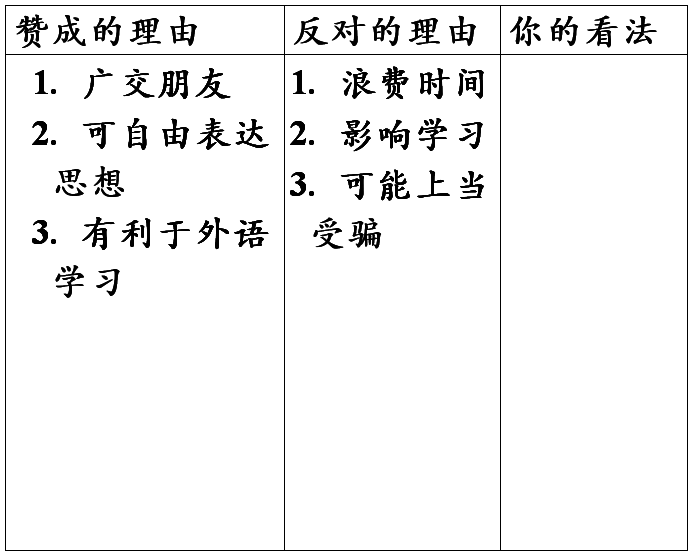
1. 文章必须包含表中全部内容。
2. 词数为100左右。
3. 参考词汇:网友 online friends 上当受骗 to be cheated
Should students make friends on line? Different people have \ hold different opinions \ attitudes.
Some people are in favor of the idea. Chatting on line, students can not only make more friends but also express their feelings and opinions more freely. What’s more, they can get help with their foreign language studies.
However, each coin has two sides. Other people hold the opposite opinion. First of all, they think making friends on line is a waste of time, which will have a bad effect on their study. What’s more, some students may get cheated on line.
As far as I am concerned, I am not in favor of the idea that students make friends on line. Students should place their study, health and safety before other things.
第二篇:机械类英语文章
CH240 planetary hoist
installation, maintenance and serance manual
Foreword
The following service instructions have been prepared to provide assembly, disassembly and maintenance information for the BRADEN
Modle CH series winch. It is suggested that before doing any work on these units, all assembly and disassembly instructions should
be read and understood.
Some pictures in this manual may show details or attachments that are different from your winch. Also, some components have been
removed for illustrative purposes.
Continuing product improvement may cause change in your winch, which are not included in this manual. Whenever a question arises
regarding your BRADEN Winch or this manual, please contact BRADEN Service Department for the latest available information.
model number and serial number
When information on a hoist is needed, always refer to the model number and serial number. Both are located on the top
of the motor side end plate as indicated above.
EXPLANATION OF MODEL NUMBER
CH 240 A - 23 090 01
construction hoist max rating design model gear ratio motor size drum size
CH Designates construction hoist (C2H designates two speed) 150 Designates 15000 LB first layer line pull
A Designates the model series relating to design changes 23 Designates total gear reduction
90 Designates hydraulic motor displacement in CU in/rev (decimal point eliminated example 090-9.0 CU in/rev)
1 Designates the drum option
General safety recommendations
1.Be certain equipment (boom, sheave blocks, pendants, etc.) is either lowered to the ground or blocked securely before servicing,
adjusting, or repairing winch.
2.Be sure personnel are clean of work area BEFORE operating winch.
3.Read all warning and caution tag information provided for safe operation and
service of winch.
4.Inspect rigging and winch at the beginning of each work shift. Defcts should be corrected immediately.
5.Keep equipment in good operating condition. Perform scheduled servicing and adjustments listed in the "Preventive Maintenance" section
of this manual.
6.An equipment warm-up procedure is recommended for all start-ups and essential at ambient temperatures below +40°F. Refer to "Warm-up
Procedure" listed in the "Preventive Maintenance" section of this manual.
7.Do not exceed the maximum pressure (PSI) or flow (GPM) stated in the winch specifications.
8.Operate winch line speeds to match job conditions.
9.Leather gloves should be used When handling wire rope.
10.Never attempt to handle wire rope when the hook end is not free.
11.When winding wire rope on the winch drum, never attempt to maintain tension by allowing wire rope to slip through hands. Alwalys use
"Hand-Over-Hand" technique.
12.Never use wire rope with broken strands. Replace wire rope.
13.Do not weld on any part of the winch.
14.Use recommended hydraulic oil and gear lubricant.
15.Keep hydraulic system clean and free from contamiation at all times.
16.Use correct anchor for wire rope and pocket in drum.
17.Do not use knots to secure or attach wire rope.
18.The BRADEN designed wire rope anchors are capable of supporting the rated load when installed properly. For additional safety, ALWAYS
maintain a minimum of five (5) wraps of wire rope on the drum.
Safety and informational callouts used in this manual include:
CAUTION
This emblem is use to warn against potential or unsafe practices which COULD result in personal injury, and product or property
damage if proper procedures are not followed.
! WARNING !
This emblem is used to warn against unsafe practices which COULD result in severe personal injury or death if proper procedures
are not followed.
Basic Operation
Description of hoist
The hoist is made up of the following sub-assemblies:
1.Hydraulic motor and brake valve
2.Drum, drum closure, ball bearing and oil seals
3.Support end plate and bearing support
4.Motor end plate and motor adapter
5.Tie plate
6.Brake clutch assembly
7.Brake cylinder assembly and multiple-disc brake parts
8.Primary, second stage and output planetary reducer assemblies
9.Ring gear
Theory of operation
The primary sun gear is directly coupled to the hydraulic motor by the inner race of the brake clutch assembly. As the motor turns in
the hoisting direction (normal clock-wise), the three planetary assemblies reduce the input speed of the motor and rotate the ring gear
and winch drum. Since the output reducer planet carrier is held from turning by the bearing support, the drum rotates in the opposite
direction of the motor input shaft. In the hoisting direction, the static brake remains fully applied and the input shaft rotates freely
through the sprag clutch. When the motor is stopped, the load tries to rotate the winch gear train in the opposite direction. The sprag
clutch on the input shaft immediately locks up, allowing the fully applied static brake to hold the load for dropping. See Dual Brake
System-Operation for a detailed description of the lowering sequence of operation.
Dual Brake System-Description
The dual brake system consists of a dynamic brake system and a static brake system.
The dynamic brake system has two operating components:
1.Brake valve assembly
2.Hydraulic motor
The brake valve is basically a counterbalance valve. It contains a check valve to allow free of oil to the motor in the hoisting direction
and a pilot operated, spring-loaded spool valve that blocks the flow of oil out of the motor then the control valve is placed in neutral.
When the control valve is placed in the lowering position, the spool valve remains closed until sufficient pilot pressure is applied to
the end of the spool to shift it against spring pressure and open a passage. After the spool valve cracks open, the pilot pressure becomes
flow-dependent and modulates the spool valve opening which controls the lowering speed. See figures 2, 3 and 4.
The static brake system has three operating componts:
1.Spring Applied, Multiple Friction Disc Static Brake
2. Brake Clutch Assembly
3.Hydraulic Piston and Cylinder
The static brake is released by the brake valve pilot pressure at a pressure lower than that required to open the pilot operated spool
valve. This sequence assures that dynamic braking takes place in the brake valve and that little, if any heat is absorbed by the friction
brake.
The friction brake is a load holding brake only and has nothing to do with dynamic braking or rate of descent of a load.
The brake clutch is splined to the primary sun gear shaft between the motor and the primary sun gear. It will allow this shaft to turn freely
in the direction to raise a load and lock up to force the brake discs to turn with the shaft in the direction to lower a load. Figures
5 and 6.
The hydraulic cylinder, when pressurized, will release the spring pressure on the brake discs, allowing the brake discs to turn freely.
Dual Brake System--Operation
When hoisting a load, the brake clutch which connects the motor shaft to the primary sun gear, allows free rotation. The sprag cams lay
over and permit the inner race to turn free of the outer race. Figure 5. The friction brake remains fully engaged. The winch, in raising
a load, is not affected by any braking action. Figure 2.
When the lifting operation is stopped, the load attempts to turn the primary sun gear in the opposite direction. This reversed input causes
the sprag cams to instantly roll upward and firmly lock the fully engaged friction brake. Figure 6.
When the winch is powered in reverse, to lower the load, the motor cannt rotate until sufficient pilot pressure is present to open the brake
valve. Figure 3&4. The friction brake within the winch will completely release at a pressure lower than that required to open the brake
valve. The extent to which the brake valve opens will determine the amount of oil that can flow through it and the speed at which the load
will be lowered . Increasing the flow of oil to the winch motor will cause the pressure to rise and the opening in the brake valve to
enlarge, speeding up the descent of the load. Decreasing this flow causes the pressure to lower and the opening in the brake valve to
decrease thus slowing the descent of the load.
When the control valve is shifted to neutral, the pressure will drop and the brake
valve will close, stopping the load. The friction brake
will engage and hold the load after the brake valve has closed.
When lowering a load very slowly for precise positioning, no oil flow actually occurs through the winch motor. The pressure will build
up to a point where the brake will release sufficiently to allow the load to rotate the motor through its own internal leakage. This
feature results in a very slow speed and extremely accurate positioning.
The friction brake receives very little wear in the lowering operation. All of the heat generated by the lowering and stopping of a load
is absorbed by the hydraulic oil where it can be readily dissipated.
Installation
General requirements
1.The hoist should be mounted with the centerline of the drum in a horizontal position. The mounting place can be rotate to any position
around this centerline.
2.When mounting the poist, use at least grade five bolts and nuts, and use both mounting holes in each end plate.
3.It is important that the hoist be mounted on a suface that will not glex when the hoist is in use, since this could bind the working
parts of the hoist. Also, be sure the hoist is mounted on a flat surface . If necessary, use shim stock to insure proper mounting.
The mounting surface should be flat within + or - 0.020 inches.
4.Hydraulic lines and components that operate the hoist should be of sufficient size to assure minimum back pressure at the hoist. The
motor manufacturer recommends that the back pressure not exceed 100 PSI for maximum motor seal life. 150 PSI is the maximum allowable
back pressure. The standard CH240A hoist is supplied with the motor intemally drained. If high back pressure are encountered, the motor
can be drained firectly to tank to improve motor seal life. To insure adequate static brake load holding ability, back pressure on the
hoist should not exceed 200 PSI. For pressure exceeding 200 PSI, consult Braden Engineering.
5.Make certain that the hoist drum is centered belind the firt sheave and the fleet angle does not exceed 11/2 degrees. The hoist should
also be mounted perpendicular to an imaginary line from the center of the drum to the firt sheave to insure even spooling.
6.The hoist directional control valve must be a three-position, four-way valve with a motor spool such that when the valve is in the
center position both work ports are opened directly to tank.
7.The hydraulic oil filter should have a 10 micron nominal rating and be a full-flow type.
8.High quality hydraulic oil is essential for satisfactory performance and long hydraulic system component life.
Oil having 150 to 330 SUS viscosity at 100°F(38°C) and viscosity index of 100 or greater will give good results under normal
temperture conditions. The use of an oil having a high viscosity index will minimize cold-start trouble and reduce the length
of warm-up periods. A high viscosity index will minimize change in viscosity with corresponding changes in temperature.
Maximum cold weather start-up viscosity should not exceed 5000 SUS with a pour point at least 20°F lower than the minimum temperature.
Under continous operating conditions the temperature of the oil at any point in the system must not exceed 180°. 120-140°F is
generally considered optimum.
In general tems; for continuous operation at ambient temperature between 50 and 110°F, use SAE 20W; for continuous operation
between 10 and 90°F, use SAE 10W; for applications colder than 10°F, contact the BRADEN Service Department. The use of
multi-viscosity oils is generally not recommended.
Wire Rope Installation
! Warning !
The cable anchors alone on hoist are not designed to hold rated loads.
Winch loads applied directly to the wire rope anchor may cause the wire rope to pull free and result in the sudden loss of load control
and cause property damage, personal injury or death. A minimum of 3 wraps of wire rope must be left on the drum barrel to achieve
rated load.
The wedge and anchor pocket must be clean and dry. The end of the wire rope being anchored to the drum must be clean and dry and not frayed.
Anything on the end of the wire rope to keep it from fraying (i.e. tape or wire) must not be in contact with the wedge when the installtion
is complete. Consult the wire rope manufacturer on the proper treatment of the dead end of the wire rope. Some rope manufacturers recommend
when using rotation resistant wire rope, that the rope end be seized, welded or brazed before inserting the wire rope into the wedge socket to
prevent core slippage or loss of rope lay.
Take the free end of the wire rope and insert it through the small opening on the cable drum. Loop the wire rope and push the free end about
3/4 of the way back through the pocket. Install the wedge as showm in figure 7, then pull the slack out of the wire rope. The "dead" end of
the rope needs to extend slightly beyond the end of the wedge as shown in figure 8.
Using a hammer and brass drift, drive the wedgeas deep into the pocket as possible to ensure it is fully seated and no further movement
is detected. Applying a load on the wire rope will also help seat the wedge in the pocket.
Check to ensure the wedge does not protrude from either end of the pocket, causing it to interfere with proper spooling of wire rope onto
the drum (see figures 9&10). If there is interference or the wedge does not seat firmly, contact the Braden Product Support Department
at 918-251-8511 to determine the proper wedge size.
It is important that the wire rope have the proper tensioning when it is installed on the drum. When the wire rope is first installed,
you should operate the hoist, with light to moderate loads, with reeving that let's you place these loads on the block and the drum with
all off the drum except for the last three wraps.
Preventive Manitenance
A regular program of preventive maintenance for your planetary winch is strongly recommended to minimize the need for emergency sergency
servicing and promote safe, reliable winch operation.
Field experience, supported by engineering tests, indicate the three (3) service procedures listed below are the Most critical to safe,
reliable winch operation and must be observed.
* Regular Gear Oil Change -every 1000 hours or six (6) months
* Use Proper Gear oil -recommended type for prevailing ambient temperature
* Annual Disassembly and Inspection of All Wear Items-in compliance with
American National Standads Institute (ANSI) specification
B30.5c 1987 and Amerian Petroleum Institute (API) recommended practice RP 2D section 3.
The following minimum service intervals are specified for operating hours of the prime mover.
1. Oil level
The gear oil level should be checked every 500 operating hours or three (3) months, whichever occurs first. To check the oil level,
remove the pluglocated in the drum support. The oil should be level with the bottom of this opening. If additional oil in need, refer
to " Recommended Planetary Gear Oil".
2. Oil Change
The gear oil should be change after the first one hundred (100) hours of operation, then every 1000 operating hours or six (6) months,
whichever occurs first. The gear oil must be changed to remove wear particles that impede the reliable and safe operation of brake clutch
and erode bearings, gears and seals. Failure to change gear oil at these suggested minimum intervals may contribute to intermittent
brake slippage which could result in property damage, severe personal injury or death.
The gear oil should also be changed whenever the ambient temperature changes significantly and an oil from a different temperature range
would be more appropriate. Oil viscosity with regard to ambient temperature is critical to reliable brake clutch operation. Our tests
indicate that excessively heavy or thick gear oil may contribute to intermittent brake clutch slippage. Make certain that the gear oil
viscosity used in your winch is correct for your prevailing ambient temperature. Failure to use the proper type and viscosity of planetary
gear oil may contribute to brake clutch slippage winch could result in property damage, severe personal injury or death. Refer to
"Recommended Planetary Gear Oil" for additional information.
3. Vent Plug
The vent plug is located in the drum support as shown. It is very important to keep this vent clean and unobstructed. Whenever gear oil
is changed, remove vent pulg, clean in solvent and reinstall.
Do not paint over the vent or replace with a solid plug.
4.Hydraulic System
The original filter element should be replaced after the first fifty (50) hours of operation, then every 500 operating hours or three (3)
months, or in accordance with the equipment manufacturer's recommendations.
5.Wire rope
Inspect entire length of wire rope according to wire rope manufacturers recommendations.
6.Mounting Bolts
Tighten all winch base mounting bolts to recommended torque after the first one hundred (100) hours of operation, then every 1000 operating
hours or six (6) months, whichever occurs first.
7. Warm-up Procdures
A warm-up procedure is recommended at each start-up and is essential at ambient temperature below +40°F (4°C).
The prime mover should be run at its lowest tecommended RPM with the hydraulic winch control valve in neutral allowing sufficient time to
warm up the system. The winch should then be operated at low speeds, froward and reverse, several times to pirme all lines with warm hydraulic
oil, and to circulate gear lubricant through the planetary gear sets.
! Warning !
Failure to properly warm up the winch, particularly under low ambient temperature conditions, may result in temporary brake slippage
due to high back pressures attempting to release the brake, which could result in property damage, severe personal injury or death.
8.Recommended Planetary Gear Oil
Field experience, supported by extensive engineering tests, indicates the use of the proper planetary gear oil is essential to reliable and
safe operation of the brake clutch and obtaining long gear train life.
! Warning !
Failure to use the proper type and viscosity of planetary gear oil may contribute to intermittent brake clutch slippage which could
result in property damage, severe personal injury or death. Some gear lubricants contain large amounts of EP (extreme pressure) and
anti-friction additives which may contribute to brake clutch slippage and damage to brake friction discs or seals. Oil viscosity
with regard to ambient temperature is also critical to reliable brake clutch operation. Our tests indicate that excessively heavy
or thick gear oil may contribute to intermittent brake clutch slippage. Make
certain that the gear oil viscosity used in your winch
is correct for your prevailing ambient temperature.
For simplicity, BRADEN has listed one (1) readily available product in each
temperature range which has been tested and found to meet our
specifications. This is not to say that other lubricant brands would not perform equally as well.
If the following lubricant brands are not available in your area, make certain certain
your lubricant vendor supplies you with oil that is
equivalent to those products listed below.
BRADEN planetary winches are factory filled with Texaco Meropa 150 or equivalent
API GL-2/3 gear oil.
9. Inspection
In compliance with ANSI specification number B30.5c1987 and API Recommended
Practice RP 2D section 3, we recommend that the winch be disassembled for a thorough inspection of all wear items every 2000 hours of operation or twelve
(12) months, whichever occurs first.
A. Bearing and Gears-- Refer to DISASSEMBLE OF WINCH, item 17 on page 19; and PLANET CARRIER SERVICE, item 3 on page 20.
B. Brake Cylinder-- Refer to MOTOR SUPPORT-BRAKE CYLINDER SERVICE, Clean and Inspect, pages 22 and 23.
C. Beake Clutch-- Refer to BRAKE CLUTCH SERVICE, item 4 on page 26
TROUBLE SHOOTING
! WARNING!
If a winch ever exhibits any sign of erratic operation, or load control difficulties (i.e.
load creeping or chattering) appropriate troubleshooting
tests and repairs should be performed immediately. Continued operation in this
death.
TROUBLE PROBABLE CAUSE REMEDY
A
The winch will not lower the load or 1.The problem could be a plugged
or loose pilot Remove the pilot hose and fitting form the not lower the load smoothly. orifice. The pilot orifice is a small pipe
plug brake valve, then use a 5/32 inch Allen manner may result in property damage, serious personal injury or
with a hole drilled through it, located behind wrench
to remove the pilot orifice. The
the pilot port fitting on the brake valve. If diameter of
the orifice is approximately
it becomes plugged, it will prevent the pilot 0.020
inches. Clean and install the pilot
pressure, from the manifold, from opening the orifice
tightly in the brake valve.
brake valve. If it become loose, it will allow
an unregulated amount of oil in to operate the brake valve which cause erratic brake valve
operation.
2.The friction brake may not be releasing as
Check brake cylinder seal as follows:
result of a defective brake cylinder seal. A. Disconnect
the swivel tee from the brake
release port. Connect a hand pump with NOTE: If the brake cylinder seal is
accurate 0-2000 psi gauge and shut-off
you will usually find oil leaking from the valve to
the -4 J.I.C. fitting in the
winch vent plug. brake release port.
B. Apply 1000 psi to the brake. Close shut-off valve and let stand for five (5) minutes.
C. If there is any loss of pressure in five (5) minutes, the brake cylinder should be
disassembled for inspection of the sealing surfaces and replacement of the seals. Refer to "Motor Support-Brake Cylinder Service".
3. Friction brake will not release as a result of Disassemble brake to inspect brake discs.
damaged brake discs. Check stack-up height as
described in
"Motor Support-Brake Cylinder Service".
B
Oil leaks from vent plug. 1. Same as A2. Same as
A2.
2. Motor seal may be defective as a result of high System back pressure must not exceed 150 psi. a defective
system back pressure or contaminated oil. Inspect
hydraulic system for a restriction
in the return line from the control valve
to the reservoir. Be sure control valve and plumbing is properly sized to winch motor.
Oil analysis may indicate contamination has worn motor shaft and seal. Thoroghly flush entire hydraulic system and install new
filters and oil. Install new motor seal.
C
The brake will not hold with the 1. Excessive system brake pressure
acting on the The same as Remedy 2 of Trouble B2.
control lever in neutral. brake release port.
2. Friction brake will not hold due to worn or Same as
Remedy 3 of Trouble A3.
damaged brake discs.
3. Brake clutch is slipping. Improper planetary gear oil
may cause the
brake clutch to slip. Drain old gear oil
and flush winch with solvent. Thoroughly
drain solvent and refill winch with recommended planetary gear oil listed in "Preventive
Maintenance".
and inspect brake clutch as described in
"Brake Clutch Service".
D
The winch will not hoist the 1. The winch may be mounted on an
uneven or flexible Reinforce mounting surface.
If necessary, use shim stock to level winch.
and binding of the gear train. Binding in the Refer
to "Winch Installation".
the rated load and cause heat. First loosen, then
evenly retighten all winch
mounting bolts to recommended torque. Brake clutch may be damaged or worn. Disassemble rated load. surface which causes distortion of the winch base gear train will absorb horsepower needed to hoist
2. System relief valve may be set too low. Relief A.
Install an accurate 0-4000 psi gauge into the
valve needs adjustment or repair. inlet port of the
brake valve.
B. Apply a stall pull load on the winch while monitoring pressure.
C. Compare gauge reading to winch specifications. Adjust relief valve as required.
NOTE: If pressure does not increase in proportion to adjustment, relief valve may be contaminated or worn out. In either case, the relief valve may require disassemble or replacement.
3. Be certain hydraulic system temperature is not Same as remedies for Trouble D1&D2.
more than 180 degrees F. Excessive hydraulic oil temperature increase motor internal leakage and Same as remedies for Trouble E2.
reduce motor performance.
4. Winch line pull rating is based on 1ST layer of Refer to winch performance charts for additional
wire rope. information.
5. Rigging and sheaves not operating efficiently. Perform rigging service as recommended by crane
manufacturer.
E
The winch runs hot. 1. Same as D1. Same as
remedies for Trouble D1.
is not more than 180 degrees F. Excessive hydraulic oil temperature may be caused by:
A. Plugged heat exchanger. Thoroughly clean exterior
and flush interior.
B. Too low or too high oil level in hydraulic Fill/drain to
proper level.
reservoir.
2. Be certain that the hydraulic system temperature
C. Same as D2. Same as remedies for Trouble D2.
D. Hydraulic pump not operating efficiently. Prime
move low on horsepower or R.P.M.
Tune/adjust prime mover.
Check suction line for damage.
If pump is belt driven, belts are slipping.
Replace/tighten belts.
Pump worn. Replace pump.
3. Excessively worn or damaged internal winch parts. Disassemble winch to inspect/replace worn parts.
F
Winch "chatters" while raising 1. Same as D2. Same as remedies for Trouble D2.
rated load.
2. Hydraulic oil flow to motor may be too low. Same as
remedies for Trouble E2.
3. Controls being operated too quickly. Conduct
operator training as required.
G
The wire rope does not spool 1. The winch may be mounted too
close to the main Check mounting distance and fleet angle. smoothly on the drum. sheave, causing the fleet angle to the more
than Reposition winch as required.
11/2 degrees.
2. The winch may not be mounted perpendicular to an Refer to "Winch Installation".
imaginary line between the center of the cable drum and the first sheave.
3. Could possibly be using the wrong lay rope. There Consult wire rope manufacturer for recommendation
is a distinct advantage in applying rope of the of
wire rope that best suits your application.
proper direction of lay. When the load is slacked
off, the several coils on the drum will stay closer together and maintain an even layer. If rope of improper lay is used, the coils will spread apart each time the load is removed.
Then, when winding is resumed, the rope has a tendency to crisscross and overlap on the drum. The result is apt to be a flattened and crushed rope.
4. The winch may have been overloaded, causing Replace wire rope and conduct operator/rigger
permanent set in the wire rope. training as requierd.
Disassemble Procedure For Hoist
1.Remove the wire rope from the hoist drum and align the drain plug in the drum
and mounting bolts. After the hoist is removed from its mounting, clean the
outside surfaces.
2.To drain the oil, screw a short piece of 1" pipe into the larger threads of the drain
hole.
3.Use a 3/8" drive extension to remove the drain plug through the pipe. If the drain
hole wear not aligned before the hoist was removed from its
mounting, the oil can be drained through the fill/vent plug in the bearing support
by turning the hoist up on the bearing support end.
4.Begin the disassembly by standing the hoist on the end opposite the motor. Tag
and remove the hydraulic hoses that connect the brake valve and
the motor (maifold in the case of a two-speed motor) to the bra release port.
5.Remove the four (4) capscrews and lockwashers securing the motor and lift the
motor off the hoist. Remove and discard the O-ring installed on
the outside of the motor pilot.
6.Remove the sixteen (16) capscrews and lockwashers from the two (2) tie plates,
and remove the plates.
7.Remove the tee fitting from the brake cylinder nipple.
8.Remove the eight (8) capscrews and lockwashers from the motor adapter, and
remove the motor adapter. Remove and discard the O-ring that was
under the motor adapter.
9.Remove the brake cylinder nipple, then remove the motor end plate. Be careful
not to damage the hydraulic fitting located in the brake housing.
10.Remove the brake clutch assembly from the brake cylinder. Rafer to the section
on disassembly of the brake clutch assembly.
11.Remove the brake plate spacer and brake and friction discs.
12.Remove the brake cylinder assembly, and place it on a clean, dry surface so as
not to damage the splines. Refer to the section on disassembly with the hole in the support end plate before removing the hoses
of the brake cylinder assembly.
13.Next, remove the primary sun gear.
14.Remove the cable drum closure by using two (2) capscrews from the motor adapter and a short piece of chain. Lift the closure out of the drum.
Remove and discard the O-ring and the seal. Inspect the bearing for wear. If replacement is necessary, use a bearing driver to remove the
bearing.
15.Remove the thrust bearing and two (2) races. Remove the spacer that locates the thrust bearing assembly.
16.Lift the primary planet assembly out of the ring gear.
NOTE: The second stage sun gear is held in the primary planet carrier with a retaining ring and will lift out with the primary planet assembly.
If the thrust washer between the primary and second stage planet assemblies stayed in the winch, remove it and set it aside with the primary
planet carrier.
Refer to the section of Disassembly of Planet Carrier.
17.Remove the snap ring from the cable drum.
18.Lift out the ring gear. Inspect the gear for abnormal wear or pitting.
19.Lift the second stage planet assembly out of the drum. The output sun gear is held in the second stage planet carrier with a retaining ring
and will lift out with the carrier assembly. If the thrust washer which is between the secondary and output planet carrier assembly stayed
in the winch, remove and set it aside with the second stage planet assembly.
CAUTION
In the following step, the output adapter on long drum CH240 units may lift out with the output planet assembly and drop unexpectedly.
20.The output planet carrier has two (2) tapped holes (1/2-13) which can be used to lift the assembly out of the ring gear. Thread two (2) eye
bolt into these holds and use them to lift the output planet assembly out of the drum. Due to the weight of the assembly, install a piece of
chain of a lifting strap between the eyebolts and use a small hoist if one is available.
21.Remove the output adapter from the bearing support splines. (units with 01 drum only)
22.On CH240 Models with the 02 drum remove the bearing support extension.
23.Lift the drum off the support end plate.
24.Turn the drum over and remove and discard the seal. Inspect the bearing in the end of drum. If replacement is necessary. Use a bearing driver
to remove the bearing.
25.On models with the 02 drum, there is a coupling between the bearing support and bearing support extension, as shown above. Check the bearing
support sealing surface for nicks and burrs. It is not necessary to remove the bearing support from the support end plate unless it has been
damaged.
BRAKE CYLINDER SERVICE
1.Turn the brake cylinder on end with the large end down. Use the special compression tool or a shop press to compress the backup plate in order to remove the retaining ring.
1.旋转刹车转盘
CAUTION
Make certain that the threaded rod of the compression tool fully engages the lower plate. If a press is used, be careful not to damage any parts
by applying too much pressure.
Remove the rataining ring with snap ring pliers. Be careful to not let the pliers slip out of the retaining ring. Release the compression tool
by holding the threaded rod stationary while backing off the nut.
2.Remove the spring guide. The backup plate, belleville springs and spring guide will come out together. Closely inspect the spring guide for
damage that might prevent the springs from moving freely in an axial direction. Also inspect the springs for cracks and material displacement.
Replace any defective parts.
铆
文章来源:华夏模具网() 钉线铝线/sell_list/keyword-%E9%93%86%E9%92%89%E7%BA%BF%E9%93%9D%E7%BA%BF
-
高考英语书面表达(写作)经典范文大全(14个类型)
高考英语书面表达经典范文大全14个类型PartOne提纲式作文1假设你是一名新闻记者请根据以下表格信息给英语报社写一篇新闻报道参考…
-
初中英语书面表达精品范文
初中英语书面表达精品范文三一内容解读1书面表达的形式多种多样但主要可分为三类应用文看图作文和提示作文2应用文包括英文通知启事便条日…
-
中考英语书面表达精选练习及参考范文
中考英语书面表达精选练习及参考范文写作在英语学习中是培养和提高语言能力的有效手段它有助于巩固和掌握所学词汇语法等语言知识有助于训练…
-
高一英语书面表达范文精编
高一英语书面表达范文精编1辽宁省沈阳二中1011学年高一上学期10月月考英语书面表达满分25分假如你叫李平你的美国笔友Tom来信询…
-
初中英语书面表达(含范文)
书面表达一20xx321许多学习和生活中的烦恼都会使人产生压力为了更好地发现及减轻同学们的心理压力你们班开展了一次以LessPre…
-
高考英语作文优秀范文分类(全)
经典范文1表达观点类在英语课堂上你喜欢你的老师授课时只用英语还是英语汉语兼用某英语杂志社就此话题邀请中学生发表看法请围绕Howdo…
-
高考英语作文优秀范文分类
背诵篇目1表达观点类在英语课堂上你喜欢你的老师授课时只用英语还是英语汉语兼用某英语杂志社就此话题邀请中学生发表看法请围绕Howdo…
-
高考英语作文优秀范文分类
高考英语满分作文1表达观点类在英语课堂上你喜欢你的老师授课时只用英语还是英语汉语兼用某英语杂志社就此话题邀请中学生发表看法请围绕H…
-
高考英语作文优秀范文分类
晨诵篇目1表达观点类在英语课堂上你喜欢你的老师授课时只用英语还是英语汉语兼用某英语杂志社就此话题邀请中学生发表看法请围绕Howdo…
-
高考英语作文优秀范文分类
晨诵篇目1表达观点类在英语课堂上你喜欢你的老师授课时只用英语还是英语汉语兼用某英语杂志社就此话题邀请中学生发表看法请围绕Howdo…
-
高考英语作文范文:作文类型及范文
考场作文TIPS一取悦评卷人1有清晰的整体脉络有自然的段间衔接经典的用词用句整齐美观的书写2润色文章原则用词老辣用句经典定语从句i…