一个8D报告的实例(英文)
一个8D报告的实例(英文)
1. Form the Team
Date Started: Sep. 22, 2002
Internal team member: A, B, C
External team member: N/A
2. Describe the Problem
One field failed unit of XXX model was returned from the customer on Sep.20. The failure occurred at the end-user’s site with the symptom described as ‘The unit burned when powered on with line and could not be powered on again.’
3. Describe the Root Cause
3.1 What Found
After carefully investigation it is found that components listed below in the XXX circuit are damaged:
Part Spec. Description D5,D6,D7,D8 XX A/XX V Rectifier Diode
3.2 Circuit Schematic
3.3 Fishbone Diagram
3.4 Experiments to Reproduce the Failure
3.4.1 D5-D8 temperature measurement
Condition: 1) The unit operates at ambient temperature; 2) Connecting a xx Ohm resistor between positive and negative terminals of the battery to stimulate very low battery voltage.
Result: Case temperature of the diodes stabilizes at about 60 degree Celsius which is much lower than the maximum rating with adequate margin.
3.4.2 Battery short circuit
Condition: Short circuit the battery and measure the current passes through D5-D8 with current probe.
Result: The current is zero
3.4.3 Low battery voltage
The unit operates with the DC power provided by a xx V(which is much lower than the nominal xx V) battery. Measure the current passes through D5-D8 and no over-current is found.
3.4.4 Over-current through D5-D8 when power on with nominal I/P AC voltage
The DC power is provided by a battery with nominal voltage. Measure the current passes through D5-D8 with current probe at the moment when power on the unit with nominal AC input voltage. Over-current is found.
3.4.5 High input AC voltage and low battery voltage when power on
Connect a xx Ohm resistor between positive and negative terminals of the battery to stimulate very low battery voltage. Measure the current passes through D5-D8 with current probe at the moment when power on the unit with xx AC. The current reaches xx A which is much larger than the maximum rating xx A and that can easily destroy the diodes.
3.5 Conclusion
Based on the above experiments, the root cause is that at the moment when power on the unit, especially with low battery voltage and high input AC voltage, out-of-spec current through the diodes presents.
4. Containment Plan
Fix the unit, replace damaged components
5. Permanent C/A Plan
1) Change Cxx from xx μF/xx V electrolytic capacitor to xx uF/xx V X-Cap to reduce the current through the rectifier when power on the unit.
2) Use an integrated rectifier to replace D5-D8.
3) RD release ECR for customer approval of the above engineering changes after the effectiveness is verified.
4) RD release ECN to validate the changes after the ECR is approved.
6. Verify the effectiveness of C/A
1) Measure the current through the integrated rectifier at the same condition of 2.4.5, no over-current is found.
2) Perform power cycling on 10 engineering changed units under the condition described at 2.4.5 for 48 hours, no failure was found.
7. Prevent Recurrence
Update the Standard Circuit Design Procedure (Doc. #: xxxxxxxx). Add an item in Section 11 – xx Circuit Design Standard, to require: 1) using X-Cap rather than electrolytic capacitor parallel with the rectifier, and, 2) using integrated rectifier rather than individual diodes in xx circuit design.
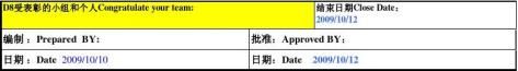
8. Congratulate the Team
The ECR has been sent to XXX (the customer name) for approval on Sep. 25. and the updated procedure will be released formally by DCC immediately when receive the approval. Thanks for the excellent work of the team.
Date Closed: Sep. 26, 2002
第二篇:8D解决报告实例


10

-
英文实习报告范文
ItisinJINXIUtravelagencythatIhavemypractice.Therearesixdepartment…
-
英语专业大学生实习报告范文
英语专业大学生实习报告范文大学的最后的一个学期,我来到一家翻译公司实习。我应聘的职务是英语校对,刚开始我对这个工作不是很了解,以为…
-
英语专业毕业实习报告范本
实习报告一、概述1、实习目的:通过阶段性时间的实习,为我们将拓宽知识面,增强感性认识,培养、锻炼我们综合运用所学的基础理论、基本技…
-
英文实习报告模板
北京农学院城乡发展学院毕业实习报告姓名学号专业商务英语班级实习单位实习时间20xx年5月30日BeijingUniversityo…
-
英语专业实习报告范文
英语专业实习报告范文英语专业实习报告20xx年的4月20日到5月8日这短短的四周我第一次学习当老师的教学实习周在这段时间我收获了很…
- 8D报告模板(中英文)
-
8d报告模板
8DREPORT异常NoSCNO管理代表ManagerRep订单数量Q39TY不良数DEFQ39TYDiscipline678由M…
-
8D报告模板 英文版
8DREPORT8DNumberIssuedToIDefectDescriptionD1SelectateamandScopeProjectPhase…
-
新8D报告中英文版
又名客诉改善行动要求单CARamp纠正预防措施整改报告编号DocNoWFQC30Page1of2又名客诉改善行动要求单CARamp…
- 8d报告
-
8D报告中英文版
1of2CTV850010114Jun20xxProcessforApprovalCARQualityEngineertosetu…