数字钟VHDL设计报告
设 计 报 告
课程名称 EDA
设计题目 数字时钟
日期 2010/6/22
目 录
摘要:... 1
关键词:数字钟 EDA VHDL语言... 1
一、设计目的... 1
二、设计内容... 1
三、设计原理... 2
1、数字钟的基本工作原理:... 2
2、数字钟的时序仿真图... 3
3、VHDL 设计... 3
四、设计仪器、设备... 4
五、设计步骤... 5
1、用VHDL程序设计... 5
步骤1:为本项设计建立文件夹... 5
步骤2:输入设计项目和存盘... 5
步骤3:选择目标器件并编译... 6
步骤4:时序仿真... 6
步骤5:引脚锁定... 9
步骤6:编程下载... 9
2、实验箱显示... 10
六、总结... 11
参考文献... 11
附录:... 11
摘要:
人类社会已进入到高度发达的信息化社会。信息化社会的发展离不开电子信息产品开发技术、产品品质的提高和进步。电子信息产品随着科学技术的进步,其电子器件和设计方法更新换代的速度日新月异。实现这种进步的主要原因就是电子设计技术和电子制造技术的发展,其核心就是电子设计自动化(EDA,Electronics Design Automation)技术,EDA技术的发展和推广应用又极大地推动了电子信息产业的发展。为保证电子系统设计的速度和质量,适应“第一时间推出产品”的设计要求,EDA技术正逐渐成为不可缺少的一项先进技术和重要工具。目前,在国内电子技术教学和产业界的技术推广中已形成“EDA热”,完全可以说,掌握EDA技术是电子信息类专业学生、工程技术人员所必备的基本能力和技能。
EDA技术在电子系统设计领域越来越普及,本设计主要利用VHDL语言在EDA平台上设计一个电子数字钟,它的计时周期为24小时,显示满刻度为24时59分59秒,另外还具有校时功能和闹钟功能。总的程序由几个各具不同功能的单元模块程序拼接而成,其中包括分频程序模块、时分秒计数和设置程序模块、比较器程序模块、三输入数据选择器程序模块、译码显示程序模块和拼接程序模块。并且使用QUARTUS II软件进行电路波形仿真,下载到EDA实验箱进行验证。
关键词:数字钟 EDA VHDL语言
一、设计目的
1、熟练地运用数字系统的设计方法进行数字系统设计;
2、能进行较复杂的数字系统设计;
3、按要求设计一个复杂的组合逻辑电路——数字钟。
二、设计内容
1、要求显示秒、分、时,显示格式如下:
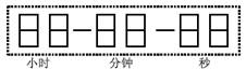
图2.1 显示格式
2、可调时,有闹钟。
三、设计原理
1、数字钟的基本工作原理:
数字钟以其显示时间的直观性、走时准确性作为一种计时工具,数字钟的基本组成部分离不开计数器,在控制逻辑电路的控制下完成预定的各项功能。数字钟的基本原理方框图如下:
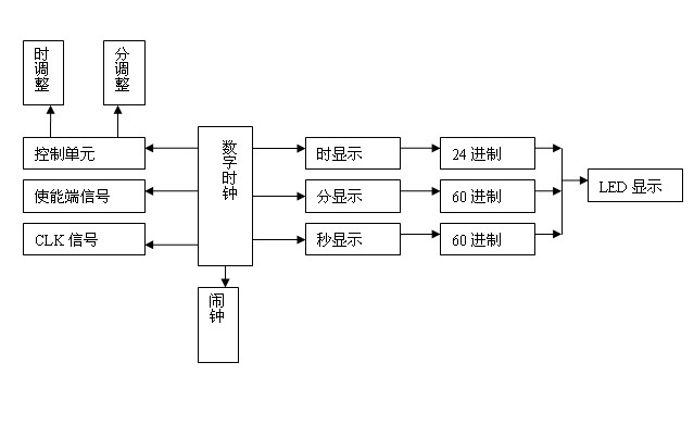
图3.1数字钟实现原理框图
1)时钟计数:完成时、分、秒的正确计时并且显示所计的数字;对秒、分
——60进制计数,即从0到59循环计数,时钟——24进制计数,即从0到23循环计数,并且在数码管上显示数值。
2)时间设置:手动调节分钟、小时,可以对所设计的时钟任意调时间,这样使数字钟真正具有使用功能。我们可以通过实验板上的key0键和key1键进行任意的调整,因为我们用的时钟信号均是经分频器后变成1HZ的,所以每LED灯变化一次就来一个脉冲,即计数一次。
3)md1为使能端,低电平时正常显示时间,高电平时设置闹钟。可以根据我们自己的需要任意设置闹钟的时间,并且闹钟可持续一分钟。
根据总体方框图及各部分分配的功能可知,本系统可以由秒计数器、分钟计数器、小时计数器、闹钟、分的调整以及小时的调整和一个顶层文件构成。采用自顶向下的设计方法,子模块利用VHDL语言设计,顶层文件用原理图的设计方法。显示:小时采用24进制,而分钟均是采用6进制和10进制的组合。
2、数字钟的时序仿真图
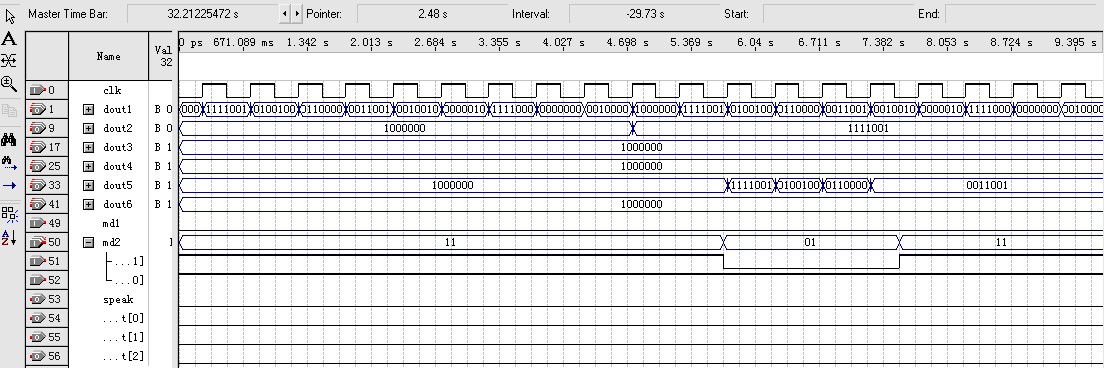
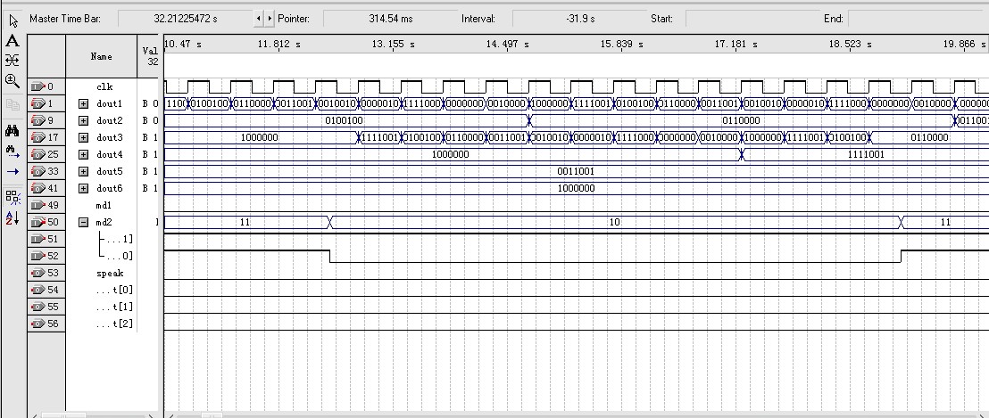
图3.3 24进制数字钟的电路图
3、VHDL 设计
library ieee;
use ieee.std_logic_1164.all;
use ieee.std_logic_unsigned.all;
entity szz is
port(clk_1:in std_logic;
md_1:in std_logic;
md_2:in std_logic_vector(1 downto 0);
light:out std_logic;
dout1:out std_logic_vector(6 downto 0);
dout2:out std_logic_vector(6 downto 0);
dout3:out std_logic_vector(6 downto 0);
dout4:out std_logic_vector(6 downto 0);
dout5:out std_logic_vector(6 downto 0);
dout6:out std_logic_vector(6 downto 0));
end entity szz;
architecture one of szz is
component led7s_10
port(a :in std_logic_vector(3 downto 0);
led7s10:out std_logic_vector(6 downto 0));
end component ;
component led7s_6
port(b :in std_logic_vector(3 downto 0);
led7s6:out std_logic_vector(6 downto 0));
end component ;
component led7s_3
port(c :in std_logic_vector(3 downto 0);
led7s3:out std_logic_vector(6 downto 0));
end component ;
component szz1
port(clk1:in std_logic;
md1:in std_logic;
md2:in std_logic_vector(1 downto 0);
speak:out std_logic;
h1:out std_logic_vector(3 downto 0);
h2:out std_logic_vector(3 downto 0);
m1:out std_logic_vector(3 downto 0);
m2:out std_logic_vector(3 downto 0);
s1:out std_logic_vector(3 downto 0);
s2:out std_logic_vector(3 downto 0));
end component;
signal x,y,z,u,v,w :std_logic_vector(3 downto 0);
begin
u1: szz1 port map(clk1=>clk_1,md1=>md_1,md2=>md_2,h1=>x,h2=>y,m1=>z,m2=>u,s1=>v,s2=>w,speak=>light) ;
u2: led7s_3 port map(c=>x,led7s3=>dout6);
u3: led7s_10 port map(a=>y,led7s10=>dout5);
u4: led7s_6 port map (b=>z,led7s6=>dout4);
u5: led7s_10 port map(a=>u,led7s10=>dout3);
u6: led7s_6 port map (b=>v,led7s6=>dout2);
u7: led7s_10 port map (a=>w,led7s10=>dout1);
end architecture one;
注:详细的VHDL文件见附录
四、设计仪器、设备
PC机一台、GW48教学实验系统一台、下载电缆一根(已接好)
五、设计步骤
1、用VHDL程序设计
步骤1:为本项设计建立文件夹
任何一项设计都是一项工程,都必须首先为此工程建立一个放置与此工程相关的所有的文件夹,在此文件夹被EDA软件默认为工作库。一个设计项目可以包含多个设计文件,一般不同的设计项目最好放在不同的文件夹中。
注意:文件名不能使用中文,且不能带空格。
步骤2:输入设计项目和存盘
1) 打开QUARTUS||,单击“file”菜单,将鼠标移到New Project Wizard 选项单击则显示如下图内容,在其中建立项目名和实体名,项目名和实体必须保持一致,最后点击finish完成
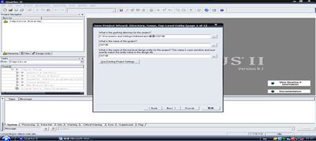
图6.1 建立 New Project
2)  在其中点击file→new,选择原理图编辑器,在这里我们建立VHDL文件,点击确定则显示下图情况,可以在里面键入程序,如下图。
图6.2 输入程序
步骤3:选择目标器件并编译
1)在Assign选项的下拉菜单中选择器件选择项Device,如图所示。在Device Family(器件序列栏)中选定目标器件对应的序列名,EPF10K10对应的是FLEX10K系列。为了选择EPF10K10LC84-4器件,应将此栏下方标有Show only Fastest Speed Grades的勾消去,以便显示出所有速度级别的器件。完成器件选择后,按OK键。
注意:所选器件必须与目标板的器件型号完全一致。
选择Cyclone Package:TQFP PIN:144 Speed grade:8
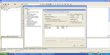
图6.3 选择目标板器件型号
3) 输入完程序以后点击工具栏右方一个紫色的三角符号“ ”,然后运行程序,如果程序出现错误在改正。

步骤4:时序仿真
1.建立波形文件:选择File->New,选择Vector Waveform File,单击OK。
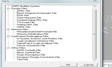
图6.4 建立波形文件
2.选择Edit->End Time选项,如图6.6所示,设定仿真时间宽度。
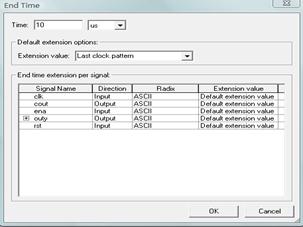
图6.5 设置仿真时间
3.双击Name下的空白处,弹出Insert Nod or Bus对话框,单击Node Finder。
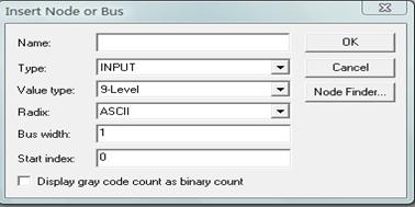
图6.6 选择添加结点设置
4.如图6.7所示选定各个选择项。
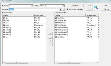
图6.7 选择结点
5.单击OK,完成引脚输入。
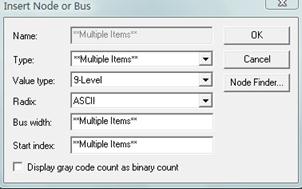
图6.8
6.加上输入信号后波形文件存盘。
7.运行仿真器。在Processing菜单下选择StartSimulation项,直到Simulator was successful出现,仿真结束。
步骤5:引脚锁定
选择Assign®Pin\Location\Chip,在跳出的窗口中的Node Name栏中用键盘输入半加器的端口名,如a、b等。如果输入的端口名正确,在右侧的Pin Type栏将显示该信号的属性。输入以后如下图,设定完成以后再运行一次程序。
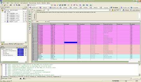
图6.9 引脚锁定
步骤6:编程下载
1)首先将下载线把计算机的打印机口与目标板(如开发板或实验板)连接好,打开电源
2)下载方式设定。选择MAX+plusII®Programmer选项,跳出下图左侧所示的编程器窗口,然后选择Options®Hardware Setup硬件设置选项,其窗口图中左侧所示。在其下拉菜单中选ByteBlaster(MV)编程方式。此编程方式对应计算机的并行口下载通道,“MV”是混合电压的意思,主要指对ALTERA的各类芯核电压(如5V、3.3V、2.5V与1.8V等)的FPGA/CPLD都能由此下载。此项设置只在初次装软件后第一次编程前进行,设置确定后就不必重复此设置了
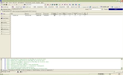
图6.10 下载编译
最后点击start按钮,进入下载模式,等待下载完成以后在试验箱上进行调试检测是否正确。
2、实验箱显示
(1)任意设置时间,让其从这一时间开始显示
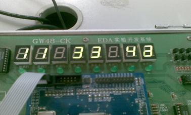
图6.13 设置时间
(2)时间显示为24进制,当时间显示到大23:59:59后将会从00:00:00开始显示
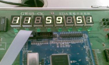
图6.14 数字钟为24进制显示
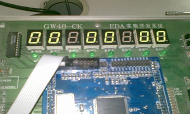
图6.15 时间跳变到00 00 00
六、总结
经过几周EDA实验的学习,使我受益匪浅。这不仅增强了我对EDA设计的兴趣,更掌握了基本的电路设计流程、方法以及技巧。具备了这些基本知识,为今后的自主学习奠定了良好的基础。在编写时可以相互借鉴,这样可以节省一定的时间,尤其是24进制的处理上,我们采用了简单的方法即可完成多个功能的顺利实现。此次设计不足之处是不能进行定时闹钟,这是有待改进的地方,当然我们也可以在闹钟的时候采用音乐提醒,可以和乐曲硬件演奏电路设计相结合,这样数字钟的功能才算是完美。
在设计中还是需要注意一些常见的问题,比如实体名、项目名等,还有在编写VHDL文件时,一些文件名也是需要注意的。
最后感谢余老师对我们的指导,以及同学们对我的帮助,使得实验能够顺利完成!
参考文献
1、沈明山编著,EDA技术及可编程器件应用实训 北京:科学出版社
2、崔建明主编,电工电子EDA仿真技术 北京:高等教育出版社,2004
3、李衍编著,EDA技术入门与提高王行 西安:西安电子科技大学出版社
4、侯继红, 李向东主编,EDA实用技术教程 北京:中国电力出版社
5、侯伯亨等,VHDL硬件描述语言与数字逻辑电路设计 西安:西安电子科技大学出版
附录:
VHDL设计程序
1、三进制
library ieee;
use ieee.std_logic_1164.all;
use ieee.std_logic_unsigned.all;
entity led7s_3 is
port(c :in std_logic_vector(3 downto 0);
led7s3:out std_logic_vector(6 downto 0));
end;
architecture one of led7s_3 is
begin
process(c)
begin
case c is
when "0000"=>led7s3<="1000000";
when "0001"=>led7s3<="1111001";
when "0010"=>led7s3<="0100100";
when others =>led7s3<="0111111";
end case;
end process;
end;
2、六进制
library ieee;
use ieee.std_logic_1164.all;
use ieee.std_logic_unsigned.all;
entity led7s_6 is
port(b :in std_logic_vector(3 downto 0);
led7s6:out std_logic_vector(6 downto 0));
end;
architecture one of led7s_6 is
begin
process(b)
begin
case b is
when "0000"=>led7s6<="1000000";
when "0001"=>led7s6<="1111001";
when "0010"=>led7s6<="0100100";
when "0011"=>led7s6<="0110000";
when "0100"=>led7s6<="0011001";
when "0101"=>led7s6<="0010010";
when others=>led7s6<="0111111";
end case;
end process;
end;
3、十进制
library ieee;
use ieee.std_logic_1164.all;
use ieee.std_logic_unsigned.all;
entity led7s_10 is
port(a :in std_logic_vector(3 downto 0);
led7s10:out std_logic_vector(6 downto 0));
end;
architecture one of led7s_10 is
begin
process(a)
begin
case a is
when "0000"=>led7s10<="1000000";
when "0001"=>led7s10<="1111001";
when "0010"=>led7s10<="0100100";
when "0011"=>led7s10<="0110000";
when "0100"=>led7s10<="0011001";
when "0101"=>led7s10<="0010010";
when "0110"=>led7s10<="1111000";
when "1000"=>led7s10<="0000000";
when "1001"=>led7s10<="0010000";
when others=>led7s10<="0111111";
end case;
end process;
end;
4、时钟
library ieee;
use ieee.std_logic_1164.all;
use ieee.std_logic_unsigned.all;
entity szz1 is
port( clk1:in std_logic;
md1:in std_logic;
md2:in std_logic_vector(1 downto 0);
speak:out std_logic;
h1:out std_logic_vector(3 downto 0);
h2:out std_logic_vector(3 downto 0);
m1:out std_logic_vector(3 downto 0);
m2:out std_logic_vector(3 downto 0);
s1:out std_logic_vector(3 downto 0);
s2:out std_logic_vector(3 downto 0));
end szz1;
architecture one of szz1 is
signal full:std_logic;
signal clk:std_logic;
signal hou1:std_logic_vector(3 downto 0);
signal hou2:std_logic_vector(3 downto 0);
signal min1:std_logic_vector(3 downto 0);
signal min2:std_logic_vector(3 downto 0);
signal seth1:std_logic_vector(3 downto 0);
signal seth2:std_logic_vector(3 downto 0);
signal setm1:std_logic_vector(3 downto 0);
signal setm2:std_logic_vector(3 downto 0);
signal sec1:std_logic_vector(3 downto 0);
signal sec2:std_logic_vector(3 downto 0);
begin
sz:process(clk1)
variable cnt8: std_logic_vector(23 downto 0);
begin
if clk1'event and clk1='1' then
if cnt8="111111111111111111111111" then
cnt8:="000000000000000000000000";
full<='1';
else cnt8:=cnt8+1;
full<='0';
end if;
end if;
end process sz;
xinhao:process(full)
variable cnt2:std_logic;
begin
if full'event and full='1' then
cnt2:=not cnt2;
if cnt2='1' then clk<='1';else clk<='0';
end if;
end if;
end process xinhao;
-----------------------------------------------小时十位
h110:process(clk,hou2,min1,min2,sec1,sec2,md1,md2)
begin
if clk'event and clk='1' then
if (hou1="0010" and hou2="0011")and(min1="0101" and min2="1001") and (sec1="0101" and sec2="1001") then
hou1<="0000";
elsif hou1="0010"and hou2="0011"and md1='0' and (md2="00"or md2="01") then--当时间为23点且处于校时状态时
hou1<="0000";
elsif (hou2="1001"and(min1="0101" and min2="1001") and (sec1="0101" and sec2="1001"))or (hou2="1001"and md1='0' and md2="01") then
hou1<=hou1+1;
end if;
end if;
end process h110;
-----------------------------------------------小时个位
h220:process(clk,min1,min2,sec1,sec2,md1,md2,hou1)
begin
if clk'event and clk='1' then
if (hou1="0010" and hou2="0011")and(((min1="0101" and min2="1001") and (sec1="0101" and sec2="1001"))or (md1='0'and md2="01")) then
hou2<="0000";
elsif hou2="1001"and(min1="0101" and min2="1001") and (sec1="0101" and sec2="1001") then
hou2<="0000";
elsif (hou2="1001"and md1='0' and md2="01")or (hou1="0010"and hou2="0011" and md1='0' and md2="00") then
hou2<="0000";--md<='1';
elsif ((min1="0101" and min2="1001") and (sec1="0101" and sec2="1001"))or (md1='0' and md2="01") then
hou2<=hou2+1;--speak<=clk;
end if;
end if;
end process h220;
-----------------------------------------------分钟十位
m110:process(clk,min2,sec1,sec2,md1,md2)
begin
if clk'event and clk='1' then
if (min1="0101" and min2="1001") and (sec1="0101" and sec2="1001") then
min1<="0000";
elsif min1="0101"and min2="1001"and (md1='0' and md2="00")then
min1<="0000";
elsif (min2="1001"and (sec1="0101" and sec2="1001")) or (min2="1001"and md1='0' and md2="10")then
min1<=min1+1;
end if;
end if;--end if;
end process m110;
----------------------------------------------分钟个位
m220:process(clk,sec1,sec2,md1,md2)
begin
if clk'event and clk='1' then
if min2="1001"and (sec1="0101" and sec2="1001")then
min2<="0000";
elsif min2="1001"and (md1='0' and md2="10")then
min2<="0000";
else if (sec1="0101" and sec2="1001") or(md1='0' and md2="10")then
min2<=min2+1;
end if;
end if;end if;
end process m220;
---------------------------------------------秒十位
s110:process(clk)
begin
if clk'event and clk='1' then
if (sec1="0101" and sec2="1001")then
sec1<="0000";
else if sec2="1001"then
sec1<=sec1+1;
end if;
end if;end if;
end process s110;
--------------------------------------------秒个位
s220:process(clk)
begin
if clk'event and clk='1' then
if sec2="1001" then
sec2<="0000";
else sec2<=sec2+1;
end if;
end if;
end process s220;
-------------------------------------------时间设置小时部分
sethour1:process(clk,seth2)
begin
if clk'event and clk='1' then
if seth1="0010"and seth2="0011" then
seth1<="0000";
elsif seth2="1001" then
seth1<=seth1+1;
end if;
end if;
end process sethour1;
-------------------------------------------
sethour2:process(clk,md1,md2,seth1)
begin
if clk'event and clk='1' then
if (seth1="0010"and seth2="0011")or seth2="1001"then
seth2<="0000";
elsif md1='1' and md2="01" then
seth2<=seth2+1;
end if;
end if;
end process sethour2;
-------------------------------------------时间设置分钟部分
setmin1:process(clk,setm2)
begin
if clk'event and clk='1' then
if setm1="0101"and setm2="1001"then
setm1<="0000";
elsif setm2="1001"then
setm1<=setm1+1;
end if;
end if;
end process setmin1;
----------------------------------------------
setmin2:process(clk,md1,md2)
begin
if clk'event and clk='1'then
if setm2="1001"then
setm2<="0000";
elsif md1='1' and md2="10"then
setm2<=setm2+1;
end if;
end if;
end process setmin2;
--------------------------------------------
--------------------------------------------闹铃
speaker:process(clk1,hou1,hou2,min1,min2)
begin
if clk1'event and clk1='1'then
if seth1=hou1 and seth2=hou2 and setm1=min1 and setm2=min2 then
speak<=clk1;
else speak<='0';
end if;
end if;
end process speaker;
xianshi :process(md1,hou1,hou2,min1,min2,sec1,sec2,seth1,seth2,setm1,setm2)
begin
if md1='0' then---------------计时时间显示和设置模式
h1<=hou1;h2<=hou2;
m1<=min1;m2<=min2;
s1<=sec1;s2<=sec2;
else -----------闹铃时间现实和设置模式
h1<=seth1;h2<=seth2;
m1<=setm1;m2<=setm2;
s1<="1111";s2<="1111";
end if;
end process xianshi;
------------------------------------------
end one;
5、主程序
library ieee;
use ieee.std_logic_1164.all;
use ieee.std_logic_unsigned.all;
entity szz is
port(clk_1:in std_logic;
md_1:in std_logic;
md_2:in std_logic_vector(1 downto 0);
light:out std_logic;
dout1:out std_logic_vector(6 downto 0);
dout2:out std_logic_vector(6 downto 0);
dout3:out std_logic_vector(6 downto 0);
dout4:out std_logic_vector(6 downto 0);
dout5:out std_logic_vector(6 downto 0);
dout6:out std_logic_vector(6 downto 0));
end entity szz;
architecture one of szz is
component led7s_10
port(a :in std_logic_vector(3 downto 0);
led7s10:out std_logic_vector(6 downto 0));
end component ;
component led7s_6
port(b :in std_logic_vector(3 downto 0);
led7s6:out std_logic_vector(6 downto 0));
end component ;
component led7s_3
port(c :in std_logic_vector(3 downto 0);
led7s3:out std_logic_vector(6 downto 0));
end component ;
component szz1
port(clk1:in std_logic;
md1:in std_logic;
md2:in std_logic_vector(1 downto 0);
speak:out std_logic;
h1:out std_logic_vector(3 downto 0);
h2:out std_logic_vector(3 downto 0);
m1:out std_logic_vector(3 downto 0);
m2:out std_logic_vector(3 downto 0);
s1:out std_logic_vector(3 downto 0);
s2:out std_logic_vector(3 downto 0));
end component;
signal x,y,z,u,v,w :std_logic_vector(3 downto 0);
begin
u1: szz1 port map(clk1=>clk_1,md1=>md_1,md2=>md_2,h1=>x,h2=>y,m1=>z,m2=>u,s1=>v,s2=>w,speak=>light) ;
u2: led7s_3 port map(c=>x,led7s3=>dout6);
u3: led7s_10 port map(a=>y,led7s10=>dout5);
u4: led7s_6 port map (b=>z,led7s6=>dout4);
u5: led7s_10 port map(a=>u,led7s10=>dout3);
u6: led7s_6 port map (b=>v,led7s6=>dout2);
u7: led7s_10 port map (a=>w,led7s10=>dout1);
end architecture one;
-
数字钟设计报告_南昌大学
数字钟设计报告学生姓名学号专业班级目录2一绪论11课程认知数字钟是采用数字电路实现对时分秒数字显示的计时装置早已成为人们日常生活中…
-
数字电子时钟课程设计报告
数字电子钟课程设计报告题目数字电子钟的设计与仿真专业机械工程前言加入世贸组织以后中国会面临激烈的竞争这种竞争将是一场科技实力管理水…
-
数字钟设计报告——数字电路实验报告
数字钟设计实验报告专业工程技术系班级电信0901班姓名XX学号XXXXXX数字钟的设计目录一前言3二设计目的3三设计任务3四设计方…
-
数字钟设计报告
目录1设计的任务与要求111数字钟的设计目的112数字钟的设计要求213数字电子钟的基本原理22实验器材和主要器件221主要器材2…
-
数字钟实验报告
数字钟实验报告课题名称:数字钟的设计与制作组员:姓名:班级:电气信息I类112班实验时间:实验地点:指导老师:一、实验目的:1.学…
-
数字钟VHDL设计报告
设计报告课程名称任课教师设计题目班级姓名学号日期在系统编程技术合肥学院课程设计报告目录摘要1关键词数字钟EDAVHDL语言1一设计…
-
EDA课程设计报告-- 数字钟(设计报告+仿真文件)
附仿真文件下载地址detailzhj88619xx4061213EDA课程设计报告课题名称姓名班级日期指导老师一设计要求说明设计并…
-
EDA课程设计报告_数字钟
目录摘要21设计目的22设计内容221设计任务222扩展23系统方案及设计原理331方案选择332数字钟的基本工作原理333底层元…
-
数字钟VHDL设计报告(EDA)
设计报告课程名称任课教师设计题目班级姓名学号日期在系统编程技术目录摘要1关键词数字钟EDAVHDL语言1一设计目的1二设计内容1三…
-
电子线路设计课程设计实验报告-多功能数字钟设计
实验报告多功能数字钟设计姓名学号班级一实验目标1掌握可编程逻辑器件的应用开发技术设计输入编译仿真和器件编程2熟悉EDA软件使用3掌…
-
数字电路课程设计-多功能数字时钟设计报告
多功能数字时钟设计报告目录一设计任务和要求2二设计的方案的选择与论证21总体电路分析22仿真分析33仿真说明3三电路设计计算与分析…