EMI测试报告解释
第13页:测试方法之EMI防辐射检测
20xx年09月03日11:13
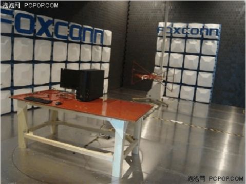
将待测的机箱摆放在中央的木质桌子上
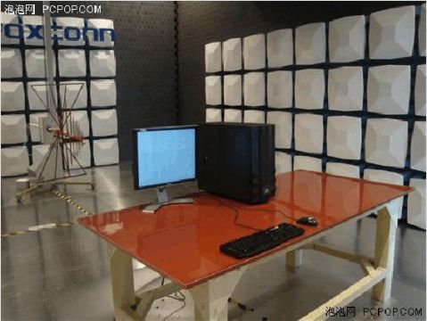
开机系统运行 检测开始
■ 如何来认读EMI测试报告
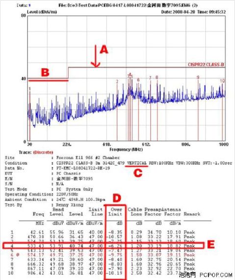
这是一份EMI测试报道,我们之后的产品介绍部分也都将以测试报告来呈现,因此为了便于读者认读报告数据,我们先来进行一下解释说明。这样一份EMI的检测报告,如图上所注有五个必须要认清的部分:
报告中五大看点
A:此处箭头所指是IEEE国际电子工程协会立法规定的EMI标准线,也就是说如若检测出超出此线,就视为EMI超标。
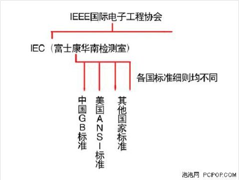
B:此处标红的线要低于IEEE国际标准,属于富士康华南检测室基于IEC标准下进行更严格的标记。关于EMI测试标准,我国仅有政府直属机关才有检测资格,而我们此次的华南检测室是基于国际IEC标准,为更加直观的介绍标准的划分,我们特以下图来进行说明。
C:此处标明的单词VERTICAL,是指天线处于垂直状态时的测试数据,EMI测试过程中,天线会分别处于水平和垂直两种状态下进行测试,我们的测试报告也分为两个部分,此处“VERTICAL”为垂直测试数据,“HORIZONTAL”则为水平
测试数据。
D:此处标明的“OverLimit”数据,是我们针对各产品进行衡量比较的,也就是说如果OverLimit这一列的数据有超出标准线的,就视为不合格。换句话说,我们应该看到如果OverLimit呈负值,而且越小,其EMI成绩则越出色。
E:在30-1000MHz范围内,系统基本运行稳定,取此频率段的数据为结果,而每款机箱都会提供10组测试成绩,以OverLimit最大值来衡量各机箱EMI之间的差异。
第二篇:Mesure the Resistance via the Wheastone Bridge 电桥法测电阻 实验报告 英语
Measure the Resistance via the Wheastone Bridge
1.The purpose:
i. To understand the principle and characteristics of the Wheatstone bridge.
ii. To understand the concept of sensitivity of bridge.
iii. Learn the “exchange measure method”, with which to eliminate the system error.
2.The apparatus:
Unknown resistances; DC power supply; galvanometer; resistor box; variable resistor; switch and other electrical components; electrical bridge.
3.Theories:
1)The principle and the structure of the Wheatstone bridge

When UC=UD
RX=
2)The sensitivity of the Wheatstone bridge
Because of the sensitivity of the galvanometer is limited, the current through the galvanometer is not truly zero, and the galvanometer cannot efficiently measure it.
The sensitivity of the bridge is defined as the ratio between the deflection of the galvanometer, Dd, and the corresponding relative value of R0.
S=
3)The “exchange measure method”.
Exchange the positions of R1 and R2, or R0 and Rx, and adjusting R0 to R0 ¢, the bridge can get a new balanced state,and RX=
Combine this equation with RX=, we can get:
RX=
This equation has nothing to do with R1 and R2. In this way we can make the error only relate to the instrument error of R0, which is the instrument error of resistor box.
4.The procedures:
1) Use simply constructed bridge to measure the metal film resistor.
Connect the circuit and measure the resistance then exchange R0 and RX measure the resistance again.
The key points:
i. Find the balance point.
ii. Measure the sensitivity of the bridge.
iii. Exchange R0 and RX measure the resistance again.
Error analysis:
The uncertainty of R0:
 apparatus=R0 apparatus=0.1%Ro+0.005(K+1)
The error caused by the sensitivity of the bridge is:
Δ =R0
=R0 (S is the sensitivity of the galvanometer)
URo=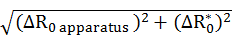
The relative uncertainty of RX is:
 =
=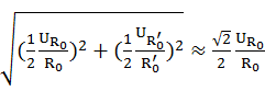 (N=1.0)
2) Use box-bridge to measure the resistance.
i. Make the reading of galvanometer back to “0” via mechanical method.
ii. Open K, press G button, adjust M and keep the galvanometer balance.
iii. Connect RX with X.
iv. Adjust the system and record the resistance R0 which make the galvanometer balance.
Error analysis:
The limit of fundamental error is:
Elim= α%(NRo+
 )
)
The error caused by the sensitivity of the bridge box is:
Δ =NR0
=NR0
The relative uncertainty of RX is:
URx=
5.Data processing:
TEST ONE.
Use simply constructed bridge to measure the metal film resistor.
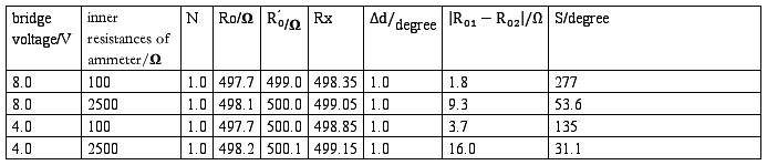
a) For U=8V Rinner=100Ω
RX== Ω=498.35Ω
S== =277
=277
The uncertainty of R0:
apparatus=R0 apparatus=0.1%Ro+0.005(K+1)
=0.1% 497.7Ω+0.005(4+1)=0.5227Ω
The error caused by the sensitivity of the bridge is:
Δ=R0=497.7Ω =0.3594Ω
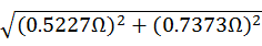
URo=
= =0.63434Ω
The relative uncertainty of RX is:
=
= =9.0123x10-4
 =
= =9.0123x10-4x498.35Ω=0.45Ω
RX =498.35
 0.45Ω
0.45Ω
b) For U=8V Rinner=2500Ω
RX== Ω=499.05Ω
S== =53.6
=53.6
The uncertainty of R0:
apparatus=R0 apparatus=0.1%Ro+0.005(K+1)
=0.1%498.1Ω+0.005(4+1)=0.5231Ω
The error caused by the sensitivity of the bridge is:
Δ=R0=498.1Ω =1.859Ω
URo=
= =1.9312Ω
The relative uncertainty of RX is:
=
= =2.7415x10-3
==2.7415x10-3x499.05Ω=1.4Ω
RX=499.01.4Ω
c) For U=4V Rinner=100Ω
RX== Ω=498.85Ω
S== =135
=135
The uncertainty of R0:
apparatus=R0 apparatus=0.1%Ro+0.005(K+1)
=0.1%497.7Ω+0.005(4+1)=0.5227Ω
The error caused by the sensitivity of the bridge is:
Δ=R0=497.7Ω =0.7373Ω
URo=
= =0.90378Ω
The relative uncertainty of RX is:
=
= =1.2840x10-3
==1.2840x10-3x498.85Ω=0.6Ω
RX=498.80.6Ω
d) For U=4V Rinner=2500Ω
RX== Ω=499.15Ω
S== =31.1
=31.1
The uncertainty of R0:
apparatus=R0 apparatus=0.1%Ro+0.005(K+1)
=0.1%498.2Ω+0.005(4+1)=0.5232Ω
The error caused by the sensitivity of the bridge is:
Δ=R0=498.2Ω =3.010Ω
URo=
= =3.0551Ω
The relative uncertainty of RX is:
=
= =4.3362x10-3
==4.3362x10-3x499.15Ω=2.2Ω
RX=499.22.2Ω
TEST TWO
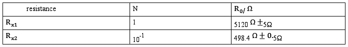
Use box-bridge to measure the resistance.
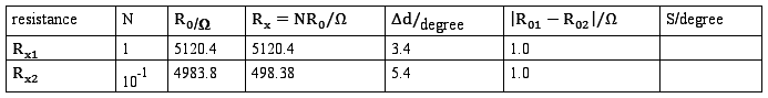
A. For resistor RX1
S== =17.4x10³
The limit of fundamental error is:
Elim=α%(NRo+)= 0.1%x5120.4Ω+1Ω=6.1204Ω
The error caused by the sensitivity of the bridge box is:
Δ=NR0=1x5120.4Ωx =0.058855Ω
The relative uncertainty of RX is:
URx==
=6Ω
RX=51206Ω
B. For resistor RX2
S== =26.9x10³
The limit of fundamental error is:
Elim=α%(NRo+)=0.1%x10-1x4983.8Ω+0.1Ω
=0.59838Ω ( =10000, and I get it from
Elim=α%(NRo+)= 0+1)
0+1)
The error caused by the sensitivity of the bridge box is:
Δ=NR0=10-1x4983.8Ωx =0.0037054Ω
The relative uncertainty of RX is:
URx=
=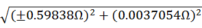
=0.6
RX=498.4 6Ω
6Ω
Discussion:
In the 1st test, “use simply constructed bridge to measure the metal film resistor”. As we can see that the “exchange measure method” eliminated the error which caused by the uncertainty of R1 and R2.Thus the main error in this experiment is the instrumental error of the resistor box (URo). The instrumental error is mainly caused by R0 apparatus. The error caused by the sensitivity of the bridge (Δ) also contributes to the error URo.
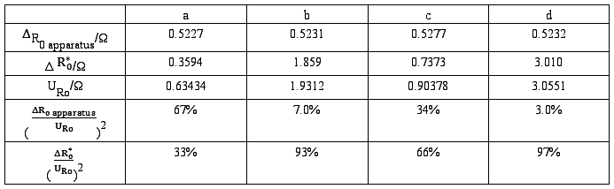
From the form, we can get that R0 apparatus plays an important role in the error when the inner resistance of the galvanometer is relative small or the voltage of the power is relative larger. On the other hand, the error caused by the sensitivity of the bridge (Δ) is the main error when the inner resistance of the galvanometer is big or the voltage of the power is small.
In the 2nd test, “use box-bridge to measure the resistance”.
The main error is the fundamental error limit (Elim) and the error caused by the sensitivity of the bridge box (Δ).
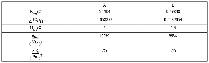
We can easily get that the main error in “use box-bridge to measure the resistance” is the fundamental error limit (Elim). And the error caused by the sensitivity of the bridge box (Δ) is so small that it can be neglected.
6.Conclusions:
From this experiment we can get that:
In the 1st test, “use simply constructed bridge to measure the metal film resistor”

In the 2nd test, “use box-bridge to measure the resistance”.
What’s more, when we use simply constructed bridge to measure the resistance, we’d better use a power supply with relative high voltage and also we should use a galvanometer with small inner resistance.
While we use the box bridge, the error mainly relate to Elim, and Elim=α%(NRo+), thus it is better to measure small resistor with box bridge.
-
系统测试报告实例
XX系统测试总结报告1引言11编写目的编写该测试总结报告主要有以下几个目的1通过对测试结果的分析得到对软件质量的评价2分析测试的过…
-
软件测试报告
测试分析报告项目名称:企业一级库库存管理系统项目负责人***编写校对审核单位:092012班第9小组20xx年11月2日系统设计与…
-
网站测试报告
网站测试报告日期20xx-6-4专业:计算机网络技术项目组:第五小组1引言1.1目的随着科技的进步,软件的规模越来越大,因此现在在…
-
系统测试报告(模板)
xxxxxxxxxxxxxxx系统测试报告xxxxxxxxxxx公司20xx年xx月版本修订记录目录1引言1111213142编写…
-
软件测试报告模板
软件测试报告模板此页为模板文档本身的版本控制记录表按模板生成的正式文档中不需要此页秘密XXXXXX软件项目系统测试报告软件测试部2…
-
一阶动态电路的响应测试实验报告
1.实验摘要1、研究RC电路的零输入响应和零状态响应。用示波器观察响应过程。电路参数:R=100K、C=10uF、Vi=5V2.从…
-
电路元件伏安特性的测量(实验报告答案)
实验一电路元件伏安特性的测量一、实验目的1.学习测量电阻元件伏安特性的方法;2.掌握线性电阻、非线性电阻元件伏安特性的逐点测试法;…
-
RC一阶电路的响应测试 实验报告
实验六RC一阶电路的响应测试一实验目的1测定RC一阶电路的零输入响应零状态响应及完全响应2学习电路时间常数的测量方法3掌握有关微分…
-
电路实验报告 常用元器件的识别与简单测试
常用元器件的识别与简单测试实验报告实验摘要根据之前所掌握的元器件基本知识识别不同元器件的种类规格及用途具体表现为运用实验室所提供的…
-
一阶动态电路测试实验报告
实验八一阶动态电路测试实验报告姓名一实验目的1测定RC一阶电路的零输入响应零状态响应及完全响应2学习电路时间常数的测量方法3掌握有…