数字逻辑实验报告
北京邮电大学
数字电路与逻辑设计实验报告

实验题目:掷骰子游戏电路的设计与实现
学生姓名:
班级:
学号:
序号:
目录
一、 设计课题的任务要求
二、 系统设计
三、 仿真波形及波形分析
四、 源程序
五、 功能说明及资源利用情况
六、 故障及问题分析
七、 总结和结论
一、 设计课题的任务要求
设计并实现一个掷骰子游戏电路。
基本要求:
1、 电路可供甲乙二人游戏,游戏者甲使用的按键为 BTN0,游戏者乙使用的按键为 BTN1。
2、 每按一次按键,代表掷一次骰子,可随机得到 1~6 范围内的两个数字。
3、 甲乙按键产生的随机数字分别用数码管 DISP0-DISP1、DISP2-DISP3 显示,并用 DISP7 显示比赛局数,比赛结束用 8×8 点阵显示获胜方,并伴有声音效果。
4、 具体游戏规则如下: (1) 第一局比赛,甲乙依次各按一次按键,按键所得两数之和为7或11者胜;若无 人取胜,则进行第二局比赛; (2) 第二局比赛,甲乙每人各按一次按键,按键所得二数之和与第一局比赛相同者获 胜,若无人获胜,则进行第三局比赛,重复进行步骤(2),直到出现胜者为止。 (3) 游戏局数最多进行六局。在第六局比赛时,若重复进行步骤(2)仍未出现胜者, 以按键所得两数之和最大者为获胜方。
提高要求: 1、 增加多人游戏的功能,数码管可分时记录显示每个游戏者的骰子点数。 2、 点阵显示增加游戏开机动画、结束动画,并伴有乐曲播放。 3、 自拟其它功能。
二、系统设计
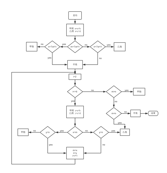
1、设计思路:按照实验要求,使用状态机分别表示游戏的不同状态;使用分频器来控制时钟;控制器实现具体的游戏规则;8*8LED点阵来显示胜负;数码管显示局数和甲乙掷出的随机数;随机数用一到六的循环产生。在编译时采用元件例化来生成各自的模块。流程图如下
 2、总体框图:
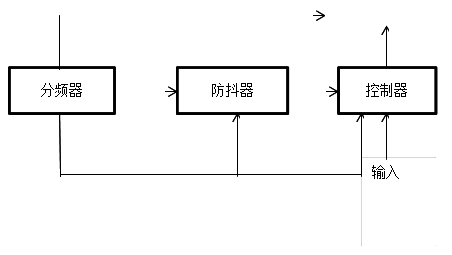
3、分块设计:
分别包括分频器、防抖器、随机数的产生、判断器、译码器和显示器等模块,综合起来实现所要求的功能。
分频器: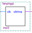
防抖器: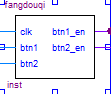
随机数的产生: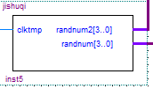
判断器: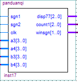
译码器: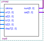
显示器: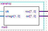
三、 仿真波形及波形分析
根据甲先乙后的顺序进行仿真如下:

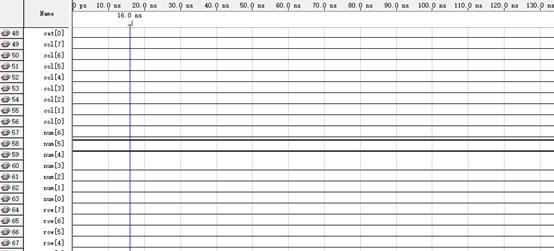
从仿真中可以看出随机数的产生,若时间轴向后移可以将游戏看得更加清楚。
四、 源程序
分频器:
library ieee;
use ieee.std_logic_1164.all;
entity fenpingqi is
port (clk:in std_logic;
clktmp:out std_logic);
end fenpingqi;
architecture a of fenpingqi is
signal tmp: integer range 0 to 499:=0;
signal clktmp1: std_logic;
begin
p3:process(clk) --frequent time
begin
if clk'event and clk='1'then
if tmp=499 then
tmp<=0;clktmp1<= not clktmp1;
else
tmp<=tmp+1;
end if;
end if;
end process p3;
clktmp<=clktmp1;
end a ;
防抖器:
library ieee;
use ieee.std_logic_1164.all;
entity fangdouqi is
port (clk,btn1, btn2 :in std_logic;
btn1_en,btn2_en :out std_logic);
end fangdouqi;
architecture a of fangdouqi is
signal tempcount1:integer range 0 to 5 :=0;
signal tempcount2:integer range 0 to 5 :=0;
begin
p5:process(clk,btn1,btn2)
begin
if clk'event and clk='1' then
if btn1='1' then
if tempcount1=5 then tempcount1<=tempcount1;
else tempcount1<=tempcount1+1;
end if;
if tempcount1=4 then btn1_en<='1';
else btn1_en<='0';
end if;
else tempcount1 <=0;
end if;
if btn2='1' then
if tempcount2=5 then tempcount2<=tempcount2;
else tempcount2<=tempcount2+1;
end if;
if tempcount2=4 then btn2_en<='1';
else btn2_en<='0';
end if;
else tempcount2 <=0;
end if;
end if;
end process p5;
end a;
计数器
library ieee;
use ieee.std_logic_1164.all;
entity jishuqi is
port (clktmp:in std_logic;
randnum2:out integer range 1 to 12;
randnum :out integer range 1 to 12);
end jishuqi;
architecture a of jishuqi is
signal randnum1: integer range 1 to 12;
signal randnum3: integer range 1 to 12;
begin
p4:process(clktmp) --counter1
begin
if clktmp'event and clktmp='1' then
if randnum1= 6 then
randnum1<=1;
else
randnum1<=randnum1+1;
end if;
if randnum3= 7 then
randnum3<=1;
else
randnum3<=randnum3+1;
end if;
end if;
if randnum3=7 then
randnum2<=1;
else
randnum2<=randnum3;
end if;
randnum<=randnum1;
end process p4;
end a;
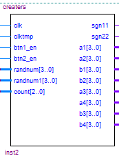
掷骰子结果的产生:
library ieee;
use ieee.std_logic_1164.all;
entity creaters is
port (clk:in std_logic;
clktmp:in std_logic;
btn1_en,btn2_en :in std_logic;
randnum,randnum1:in integer range 1 to 12;
count:in integer range 0 to 5;
sgn11,sgn22 :out std_logic;
a1,a2,b1,b2:out integer range 1 to 12;
a3,a4,b3,b4:out integer range 1 to 12);
end creaters;
architecture a of creaters is
signal a11,a22,b11,b22: integer range 1 to 12:=1;
signal a33,a44,b33,b44: integer range 1 to 12;
signal sgn1,sgn2:std_logic:='0';
begin
p1:process (a11,a22,a33,sgn1,sgn2,b11,b22,b33,btn1_en,btn2_en,clktmp)
begin
if clktmp'event and clktmp='1'then
if sgn1='1'and sgn2='1'then
sgn1<='0';sgn2<='0';
end if;
if btn1_en='1' and sgn1='0' then
sgn1<='1';
a11<=randnum; --get rand num;
a22<=randnum1;
a33<=randnum1+randnum;
if count=0 then
a44<=randnum1+randnum;
end if;
end if;
if btn2_en='1' and sgn1='1'and sgn2='0' then
sgn2<='1';
b11<=randnum;
b22<=randnum1;
b33<=randnum1+randnum;
if count=0 then
b44<=randnum1+randnum;
end if;
end if;
end if;
a1<=a11;
a2<=a22;
a3<=a33;
b1<=b11;
b2<=b22;
b3<=b33;
a4<=a44;
b4<=b44;
sgn11<=sgn1;
sgn22<=sgn2;
end process p1;
end a ;
判断器:
library ieee;
use ieee.std_logic_1164.all;
entity panduanqi is
port (sgn1,sgn2 :in std_logic;
clk:in std_logic;
a3,a4,b3,b4: in integer range 1 to 12;
disp77: out integer range 1 to 6;
count1:out integer range 0 to 5;
winsgn :out std_logic_vector(1 downto 0));
end panduanqi;
architecture a of panduanqi is
signal count : integer range 0 to 5:=0;
signal disp7 : integer range 0 to 5:=1;
begin
p7:process(clk,a3,a4,b3,b4,sgn1,sgn2) --judgment
begin
if clk'event and clk='1' then
if sgn1='1'and sgn2='1'then 规定甲先掷乙后掷
if count=0 then
if (a3=11 or a3=7) then winsgn<="10"; disp7<=disp7+1 ;count<=0;
elsif (b3=11 or b3=7) then winsgn<="01"; disp7<=disp7+1 ;count<=0;
else count<=count+1;
end if;
elsif count=5 then
if (a3=11 or a3=7 ) then winsgn<="10";
elsif (b3=11 or b3=7) then winsgn<="01";
elsif a3>b3 then winsgn<="10";
else winsgn<="01";
end if;
disp7<=disp7+1 ;count<=0;
else
if a3=a4 then winsgn<="10";disp7<=disp7+1 ;count<=0;
elsif b3=b4 then winsgn<="01";disp7<=disp7+1 ;count<=0;
else count<=count+1;
end if;
end if;
end if;
end if;
count1<=count;
if (disp7=7)then
disp77<=1;
else
disp77<=disp7;
end if;
end process p7;
end a;
译码器:
library ieee;
use ieee.std_logic_1164.all;
entity yimaqi is
port (clktmp:in std_logic;
a1,a2,b1,b2:in integer range 1 to 12;
disp7: in integer range 1 to 6;
num : out std_logic_vector(6 downto 0);
cat : out std_logic_vector(5 downto 0));
end yimaqi;
architecture a of yimaqi is
signal tempcat: std_logic_vector(5 downto 0);
signal tempnum: integer range 0 to 6:=1;
signal num1: std_logic_vector(6 downto 0);
signal cycle :integer range 0 to 4:=0;
begin
p6:process(clktmp) --translate the num1 to right num;
begin
if clktmp'event and clktmp='1' then
if(cycle=4)then
cycle<=0;
else
cycle<= cycle+1;
end if;
end if;
case cycle is
when 0 => tempnum<=a1; tempcat<="111110";
when 1 => tempnum<=a2; tempcat<="111101";
when 2 => tempnum<=b1; tempcat<="111011";
when 3 => tempnum<=b2; tempcat<="110111";
when 4 => tempnum<=disp7; tempcat<="011111";
end case;
case tempnum is
when 0=>num1<="1111110";
when 1=>num1<="0110000";
when 2=>num1<="1101101";
when 3=>num1<="1111001";
when 4=>num1<="0110011";
when 5=>num1<="1011011";
when 6=>num1<="1011111";
end case;
num<=num1;
cat<=tempcat;
end process p6;
end a;
显示器:
library ieee;
use ieee.std_logic_1164.all;
entity xianshiqi is
port (clk:in std_logic;
winsgn: in std_logic_vector(1 downto 0);
row: out std_logic_vector(7 downto 0);
col: out std_logic_vector(7 downto 0)
);
end xianshiqi;
architecture a of xianshiqi is
signal cyc :integer range 0 to 7:=0;
signal row1 :std_logic_vector(7 downto 0);
signal col1 :std_logic_vector(7 downto 0);
begin
p8:process(clk)
begin
if clk'event and clk='1' then
if cyc=7 then
cyc<=0;
else
cyc<=cyc+1;
end if;
if winsgn="10"then
case cyc is
when 0=>row1<="01111111";col1<="01111100";
when 1=>row1<="10111111";col1<="01010100";
when 2=>row1<="11011111";col1<="01111100";
when 3=>row1<="11101111";col1<="01010100";
when 4=>row1<="11110111";col1<="01111100";
when 5=>row1<="11111011";col1<="00010000";
when 6=>row1<="11111101";col1<="00010000";
when 7=>row1<="11111110";col1<="00010000";
end case;
elsif winsgn= "01"then
case cyc is
when 0=>row1<="01111111";col1<="11111111";
when 1=>row1<="10111111";col1<="01000000";
when 2=>row1<="11011111";col1<="00100000";
when 3=>row1<="11101111";col1<="00010000";
when 4=>row1<="11110111";col1<="00001000";
when 5=>row1<="11111011";col1<="00000100";
when 6=>row1<="11111101";col1<="10000010";
when 7=>row1<="11111110";col1<="11111111";
end case;
else
end if;
end if;
row<=row1;
col<=col1;
end process p8;
end a;
五、 功能说明及资源利用情况
分频器对固有频率分频提供给控制器、译码器、显示器合适的时钟;防抖器通过改变频率有效防止毛刺出现,使整个系统工作更加稳定;计数器及骰子结果的产生通过一到六的循环,同时在时钟作用下取数实现骰子数的随机出现;判断器则根据游戏规则采用状态机在时钟作用下来实现,设置变量规定甲乙投掷的顺序;译码器是使数码管在循环扫描作用下实现对掷出骰子数及局数的显示;8*8LED点阵编程控制行列高低电平同时循环扫描来实现对甲乙胜负的显示。所有模块在分频器作用下综合起来一起工作实现掷骰子的游戏。采用元件例化,尽可能提高资源利用率。
六、 故障及问题分析
初次编译程序,在调试过程中,系统工作不稳定,不能跟随按键及时显示,在老师的建议下加入了防抖器,使得系统的工作更稳定;
8*8LED点阵在显示时不稳定,有些地方有不应该亮的点亮起,经过反复试验,与同学交流,改变了行和列的编译方式,解决了问题;
8*8LED点阵显示亮度不够,改变了频率;
初次编译时,甲乙的投掷先后易引起混乱,引入了变量规定甲乙的先后顺序。
七、 总结和结论
在这次数电实验中我学到了很多。在初次拿到题目时比较混乱,不知从何处下手,通过与同学讨论,学习VHDL的相关内容,思路也渐渐清晰起来,画出了流程图及模块分布。在编写程序的过程中,采纳建议使用了元件例化,使整个系统更加清晰,编写更加有的放矢,纠错也更容易,通过一次次的调试改进,加防抖器及改变频率,终于基本完成了游戏的设计。在编写过程中最为困难的是8*8LED点阵的显示,之前对这个器件不太了解,查了好多资料弄清楚他的工作原理、编写方法,后来又在反复调试中改进,实现了其完美的显示。
我认识到在做实验时,一定要积极主动地去学习,查资料,不要怕犯错,要坚持不懈,并且及时与老师同学沟通,取长补短,发现不足之处。要积极地去实践,才可以真正提高自己的逻辑思维和动手能力。
-
数字逻辑实验报告1
《数字逻辑实验》报告1姓名xxx学号xxxxxxxx教师xxx时间xxx地点xxx楼xxx机房机位一.与非门逻辑功能测试实验1.实…
- 数字逻辑第3次实验报告
-
北邮 数字逻辑实验报告
北京邮电大学课程设计报告数字逻辑课程设计目录实验一交通灯控制器设计实验二电子钟设计实验三药片装瓶系统设计附数字逻辑课程设计调试日志…
-
数字逻辑实验报告
课程设计报告题目:常用中规模集成电路的VHDL设计计算机科学与技术学院实验一:异步时序逻辑电路的设计一、实验目的熟悉并掌握脉冲异步…
-
数字逻辑实验预习报告
实验一组合逻辑电路的分析一实验目的1掌握一般组合电路的分析与设计方法2用实验验证所设计电路的逻辑功能3掌握半加器和全加器的逻辑功能…
-
大连海事大学数字逻辑电路课程设计实验总结报告
数字逻辑电路课程设计实验总结报告题目一:用J-K触发器设计13进制加法计数器一、设计过程:参见设计实验报告(真值表,卡诺图)。二、…
-
数字电路实验心得体会
数字电路实验心得体会数字电路实验心得体会一数字电路实验心得在实验具体操作的过程中对理论知识半加器和全加器也有了更近一步的理解真正达…
-
数字电路与逻辑设计实验报告1-深圳大学
深圳大学实验报告课程名称学院计算机与软件学院实验时间实验报告提交时间教务部制注1报告内的项目或内容设置可根据实际情况加以调整和补充…
-
数字电路与数字逻辑大型实验报告
数字电路与数字逻辑大型实验报告1一实验内容一QuartusII操作练习1用原理图输入法设计一个3线8线译码器二数字频率计设计三倒计…
- 数字逻辑实验报告:计数器及其应用
-
数字逻辑实验报告二
数字逻辑实验报告学院专业班级学号姓名课题指导教师报告成绩日期年月日11数据选择器和译码器功能验证一实验目的和要求1使用EDA软件验…