路由器的基本配置实验报告
实验4 路由器的基本配置
1. 按照环境的要求,建立实验的拓扑结构。
2. 配置六台主机的IP地址
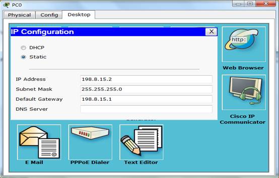
⑴ 配置198.8.15.0网络中的两台主机的地址分别是198.8.15.2和198.8.15.3。
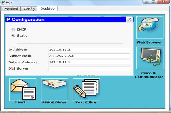
 ⑵ 配置193.10.18.0网络中的两台主机的地址分别是193.10.18.2和193.10.18.3。
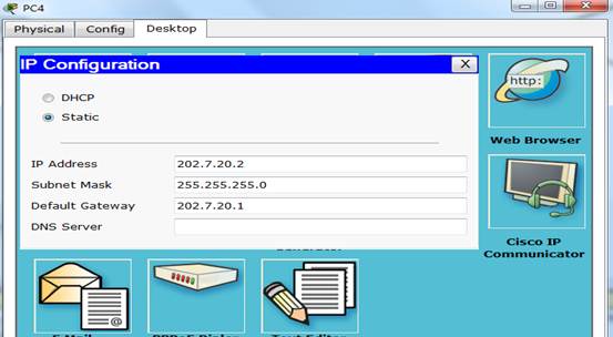
 ⑶ 配置202.7.20.0网络中的两台主机的地址分别是202.7.20.2和202.7.20.3。
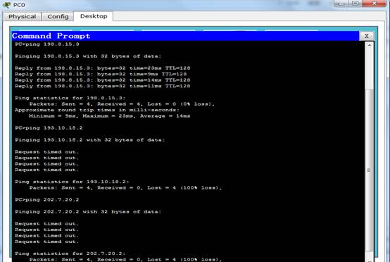
 ⑷ 测试六台主机之间的连通性,并记录测试结果。
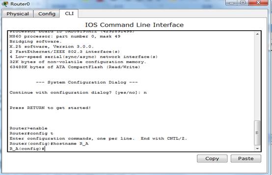
 3. 配置路由器A的基本参数。
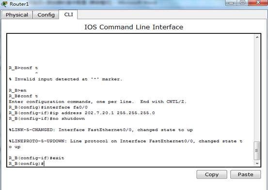
⑴ 进入到路由器的全局配置模式。命令如下:
Router0#config termainal
⑵ 配置路由器A的名称为Route_A。命令如下:
Router0<config>#hostname Router_A
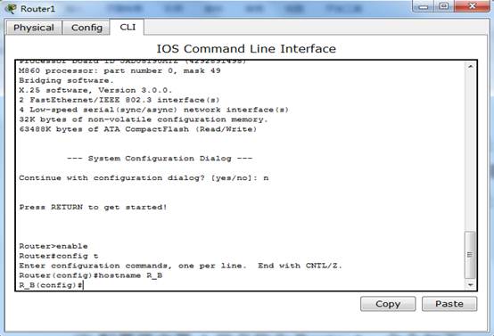
 4. 配置路由器B的基本参数
⑴ 进入到路由器的全局配置模式。
Router1#config termainal
⑵ 配置路由器B的名称为Route_B。
Router1<config>#hostname Router_B
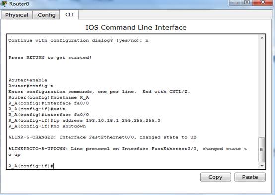
 5. 配置路由器A上各端口的地址
⑴ 设置路由器A的f0/0端口的IP地址为193.10.18.1,子网掩码为 255.255.255.0。命令如下:
Router_A<config>#interface f0/0
Router_A<config-if>#ip address 193.10.18.1 255.255.255.0
Router_A<config-if>#no shutdown
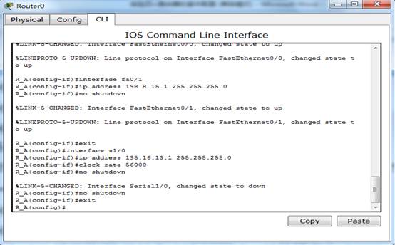
 ⑵ 设置路由器A的f0/1端口的IP地址为198.8.15.1,子网掩码为 255.255.255.0 。
Router_A<config>#interface f0/1
Router_A<config-if>#ip address 198.8.15.1 255.255.255.0
Router_A<config-if>#no shutdown
 ⑶ 设置路由器A的s1/0端口的IP地址为195.16.13.1,时钟频率为56000,子网掩码为 255.255.255.0 。命令如下:
Router_A<config>#interface s1/0
Router_A<config-if>#ip address 195.16.13.1 255.255.255.0
Router_A<config-if>#clock rate 56000
Router_A<config-if>#no shutdown
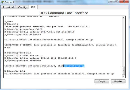
 6. 配置路由器B上各端口的地址
⑴ 设置路由器B的f0/0端口的IP地址为202.7.20.1,子网掩码为 255.255.255.0。
Router_B<config>#interface f0/0
Router_B<config-if>#ip address 202.7.20.1 255.255.255.0
Router_B<config-if>#no shutdown
 ⑵ 设置路由器B的s1/0端口的IP地址为195.16.13.2,时钟频率为56000,子网掩码为 255.255.255.0 。
Router_B<config>#interface s1/0
Router_B<config-if>#ip address 195.16.13.2 255.255.255.0
Router_B<config-if>#clock rate 56000
Router_B<config-if>#no shutdown
 7. 用命令测试各PC间的连通性,并记录测试结果。
 8. 在路由器A上设置静态路由
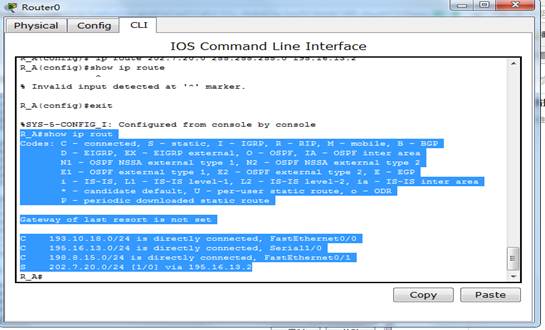
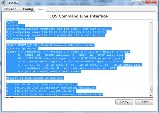
⑴ 使用命令show ip route查看路由器A的路由表信息。
⑵ 使用命令clear ip route命令清空路由表。
⑶ 使用no route rip命令删除rip路由配置。
⑷ 在路由器A的全局配置模式下,设置到达202.7.20.0网络的静态路由表项。命令如下:
Router_A<config># ip route 202.7.20.0 255.255.255.0 195.16.13.2
 ⑸ 显示路由器A上的路由表信息。
Router_A#show ip route
 9. 在路由器B上设置静态路由
⑴ 使用命令show ip route查看路由器B的路由表信息。
⑵ 使用命令clear ip route命令清空路由表。
⑶ 使用no route rip命令删除rip路由配置。
⑷ 在路由器B的全局配置模式下,设置到达193.10.18.0网络的静态路由表项。命令如下:
Router_B<config># ip route 193.10.18.0 255.255.255.0 195.16.13.1
⑸ 在路由器B的全局配置模式下,设置到达198.8.15.0网络的静态路由表项。命令如下:Router_B<config># ip route 198.8.15.0 255.255.255.0 195.16.13.1
⑹ 显示路由器B上的路由表信息。命令:
Router_B#show ip route
 10.测试主机之间的连通性
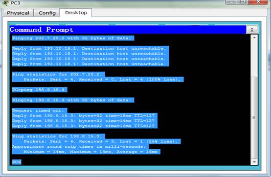
⑴ 使用ping命令测试六台主机之间的连通性。
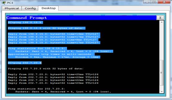
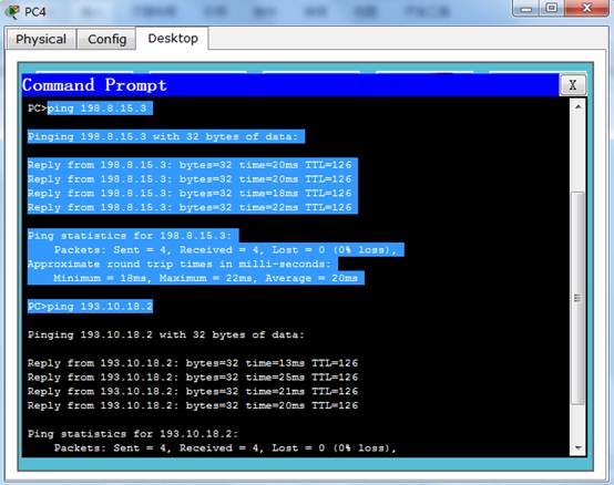 ⑵ 记录测试的结果,并且与第7步结果进行比较。
答案:第七步的ping命令测试结果是只是0主机和1通,主机2和3通,主机4和5通,其他的不通,但是在第10 步中,结果全部互相通,这表示静态路由正确的
第二篇:实验四_路由器的基本配置实验报告
实验四 路由器基本配置
一、实验目的
1、熟练掌握配置静态路由;
2、学习使用路由总结。
二、实验内容
1、拓扑结构图
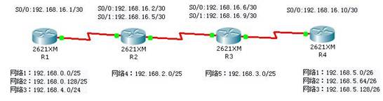
2、网络规划
(1)网络规划
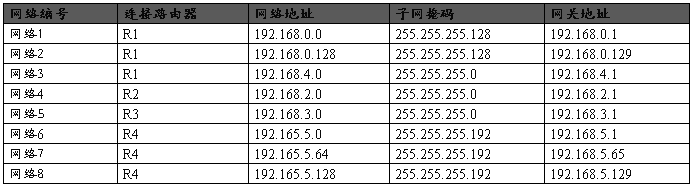
(2)IP地址分配
3、进行路由器基本配置
(1)路由器选择2621XM,为每台路由器安装模块WIC-2T,以便配置串行线路;
(2)修改路由器名称。
4、配置环回端口
为每个网络在相应的路由器上创建一个环回端口,并将端口地址设为该网络的网关地址。
(1)配置R1环回端口:
R1>en
R1r#conf t
Enter configuration commands, one per line. End with CNTL/Z.
R1(config)#interface loopback0
%LINK-5-CHANGED: Interface Loopback0, changed state to up
%LINEPROTO-5-UPDOWN: Line protocol on Interface Loopback0, changed state to up
R1(config-if)#ip address 192.168.0.1 255.255.255.128
R1(config-if)#exit
R1(config)#interface loopback1
%LINK-5-CHANGED: Interface Loopback1, changed state to up
R1(config-if)#
%LINEPROTO-5-UPDOWN: Line protocol on Interface Loopback1, changed state to up
R1(config-if)#ip address 192.168.0.129 255.255.255.128
R1(config-if)#exit
R1(config)#interface loopback2
%LINK-5-CHANGED: Interface Loopback2, changed state to up
%LINEPROTO-5-UPDOWN: Line protocol on Interface Loopback2, changed state to up
R1(config-if)#ip address 192.168.4.1 255.255.255.0
(2)配置R2环回口:
R2>en
R2#conf t
Enter configuration commands, one per line. End with CNTL/Z.
R2(config)#interface loopback0
%LINK-5-CHANGED: Interface Loopback0, changed state to up
%LINEPROTO-5-UPDOWN: Line protocol on Interface Loopback0, changed state to up
R2(config-if)#ip address 192.168.2.1 255.255.255.0
(3)配置R3环回口:
R3>en
R3#conf t
Enter configuration commands, one per line. End with CNTL/Z.
R3(config)#interface loopback0
%LINK-5-CHANGED: Interface Loopback0, changed state to up
%LINEPROTO-5-UPDOWN: Line protocol on Interface Loopback0, changed state to up
R3(config-if)#ip address 192.168.3.1 255.255.255.0
(4)配置R4环回口:
R4>en
Router#conf t
Enter configuration commands, one per line. End with CNTL/Z.
R4(config)#interface loopback0
%LINK-5-CHANGED: Interface Loopback0, changed state to up
%LINEPROTO-5-UPDOWN: Line protocol on Interface Loopback0, changed state to up
R4(config-if)#ip address 192.168.5.1 255.255.255.192
R4(config-if)#interface loopback1
%LINK-5-CHANGED: Interface Loopback1, changed state to up
R4(config-if)#
%LINEPROTO-5-UPDOWN: Line protocol on Interface Loopback1, changed state to up
R4(config-if)#ip address 192.168.5.65 255.255.255.192
R4(config-if)#interface loopback2
%LINK-5-CHANGED: Interface Loopback2, changed state to up
%LINEPROTO-5-UPDOWN: Line protocol on Interface Loopback2, changed state to up
R4(config-if)#ip address 192.168.5.129 255.255.255.192
5、进行网络连通测试
在4个路由器上使用ping命令分别测试每个网络的连通情况。
附R1运行ping测试效果:
R1#ping 192.168.0.1
Type escape sequence to abort.
Sending 5, 100-byte ICMP Echos to 192.168.0.1, timeout is 2 seconds:
!!!!!
Success rate is 100 percent (5/5), round-trip min/avg/max = 0/1/3 ms
R1#ping 192.168.0.129
Type escape sequence to abort.
Sending 5, 100-byte ICMP Echos to 192.168.0.129, timeout is 2 seconds:
!!!!!
Success rate is 100 percent (5/5), round-trip min/avg/max = 1/2/3 ms
R1#ping 192.168.4.1
Type escape sequence to abort.
Sending 5, 100-byte ICMP Echos to 192.168.4.1, timeout is 2 seconds:
!!!!!
Success rate is 100 percent (5/5), round-trip min/avg/max = 1/3/5 ms
R1r#ping 192.168.2.1
Type escape sequence to abort.
Sending 5, 100-byte ICMP Echos to 192.168.2.1, timeout is 2 seconds:
.....
Success rate is 0 percent (0/5)
R1#ping 192.168.3.1
Type escape sequence to abort.
Sending 5, 100-byte ICMP Echos to 192.168.3.1, timeout is 2 seconds:
.....
Success rate is 0 percent (0/5)
R1#ping 192.168.5.1
Type escape sequence to abort.
Sending 5, 100-byte ICMP Echos to 192.168.5.1, timeout is 2 seconds:
.....
Success rate is 0 percent (0/5)
R1#ping 192.168.5.65
Type escape sequence to abort.
Sending 5, 100-byte ICMP Echos to 192.168.5.65, timeout is 2 seconds:
.....
Success rate is 0 percent (0/5)
R1#ping 192.168.5.129
Type escape sequence to abort.
Sending 5, 100-byte ICMP Echos to 192.168.5.129, timeout is 2 seconds:
.....
Success rate is 0 percent (0/5)
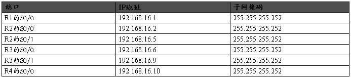
6、配置路由器端口
为4个路由器的串行端口配置IP地址,注意要在DCE设备上配置时钟,时钟波特率为64000。然后打开端口。
7、配置静态路由
(1)在R1上配置静态路由。
R1(config)#ip route 192.168.2.0 255.255.255.0 S0/0
R1(config)#ip route 192.168.3.0 255.255.255.0 S0/0
R1(config)#ip route 192.168.5.0 255.255.255.192 S0/0
R1(config)#ip route 192.168.5.64 255.255.255.192 S0/0
R1(config)#ip route 192.168.5.128 255.255.255.192 S0/0
R1(config)#ip route 192.168.16.4 255.255.255.252 S0/0
R1(config)#ip route 192.168.16.8 255.255.255.252 S0/0
(2)在R2上配置静态路由。
R2(config)#ip route 192.168.0.0 255.255.255.128 S0/0
R2(config)#ip route 192.168.0.128 255.255.255.128 S0/0
R2(config)#ip route 192.168.4.0 255.255.255.0 S0/0
R2(config)#ip route 192.168.3.0 255.255.255.0 S0/1
R2(config)#ip route 192.168.5.0 255.255.255.192 S0/1
R2(config)#ip route 192.168.5.64 255.255.255.192 S0/1
R2(config)#ip route 192.168.5.128 255.255.255.192 S0/1
R2(config)#ip route 192.168.16.8 255.255.255.252 S0/1
(3)在R3上配置静态路由。
R3(config)#ip route 192.168.0.0 255.255.255.128 S0/0
R3(config)#ip route 192.168.0.128 255.255.255.128 S0/0
R3(config)#ip route 192.168.4.0 255.255.255.0 S0/0
R3(config)#ip route 192.168.2.0 255.255.255.0 S0/0
R3(config)#ip route 192.168.5.0 255.255.255.192 S0/1
R3(config)#ip route 192.168.5.64 255.255.255.192 S0/1
R3(config)#ip route 192.168.5.128 255.255.255.192 S0/1
R3(config)#ip route 192.168.16.0 255.255.255.252 S0/0
(4)在R4上配置静态路由。
R4(config)#ip route 192.168.0.0 255.255.255.128 S0/0
R4(config)#ip route 192.168.0.128 255.255.255.128 S0/0
R4(config)#ip route 192.168.4.0 255.255.255.0 S0/0
R4(config)#ip route 192.168.2.0 255.255.255.0 S0/0
R4(config)#ip route 192.168.3.0 255.255.255.0 S0/0
R4(config)#ip route 192.168.16.0 255.255.255.252 S0/0
R4(config)#ip route 192.168.16.4 255.255.255.252 S0/0
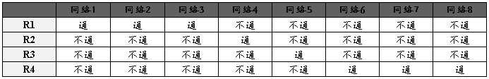
8、查看4个路由器的路由表,并记录
R1#show ip route
(1) R1路由表
192.168.0.0/25 is subnetted, 2 subnets
C 192.168.0.0 is directly connected, Loopback0
C 192.168.0.128 is directly connected, Loopback1
S 192.168.2.0/24 is directly connected, Serial0/0
S 192.168.3.0/24 is directly connected, Serial0/0
C 192.168.4.0/24 is directly connected, Loopback2
192.168.5.0/26 is subnetted, 3 subnets
S 192.168.5.0 is directly connected, Serial0/0
S 192.168.5.64 is directly connected, Serial0/0
S 192.168.5.128 is directly connected, Serial0/0
192.168.16.0/30 is subnetted, 3 subnets
C 192.168.16.0 is directly connected, Serial0/0
(2) R2路由表
192.168.0.0/25 is subnetted, 2 subnets
S 192.168.0.0 is directly connected, Serial0/0
S 192.168.0.128 is directly connected, Serial0/0
C 192.168.2.0/24 is directly connected, Loopback0
S 192.168.3.0/24 is directly connected, Serial0/1
S 192.168.4.0/24 is directly connected, Serial0/0
192.168.5.0/26 is subnetted, 3 subnets
S 192.168.5.0 is directly connected, Serial0/1
S 192.168.5.64 is directly connected, Serial0/1
S 192.168.5.128 is directly connected, Serial0/1
192.168.16.0/30 is subnetted, 3 subnets
C 192.168.16.0 is directly connected, Serial0/0
(3) R3路由表
192.168.0.0/25 is subnetted, 2 subnets
S 192.168.0.0 is directly connected, Serial0/0
S 192.168.0.128 is directly connected, Serial0/0
S 192.168.2.0/24 is directly connected, Serial0/0
C 192.168.3.0/24 is directly connected, Loopback0
S 192.168.4.0/24 is directly connected, Serial0/0
192.168.5.0/26 is subnetted, 3 subnets
S 192.168.5.0 is directly connected, Serial0/1
S 192.168.5.64 is directly connected, Serial0/1
S 192.168.5.128 is directly connected, Serial0/1
192.168.16.0/30 is subnetted, 3 subnets
S 192.168.16.0 is directly connected, Serial0/0
(4) R4路由表
192.168.0.0/25 is subnetted, 2 subnets
S 192.168.0.0 is directly connected, Serial0/0
S 192.168.0.128 is directly connected, Serial0/0
S 192.168.2.0/24 is directly connected, Serial0/0
S 192.168.3.0/24 is directly connected, Serial0/0
S 192.168.4.0/24 is directly connected, Serial0/0
192.168.5.0/26 is subnetted, 3 subnets
C 192.168.5.0 is directly connected, Loopback0
C 192.168.5.64 is directly connected, Loopback1
C 192.168.5.128 is directly connected, Loopback2
192.168.16.0/30 is subnetted, 3 subnets
S 192.168.16.0 is directly connected, Serial0/0
S 192.168.16.4 is directly connected, Serial0/0
C 192.168.16.8 is directly connected, Serial0/0
9、进行网络连通测试
在4个路由器上使用ping命令分别测试每个网络的连通情况。
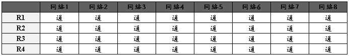
10、使用路由总结
将网络1、网络2进行路由总结。
将网络6、网络7、网络8进行路由总结。
(1)在R1上,路由表可以简化为:
R1(config)#ip route 192.168.2.0 255.255.255.0 S0/0
R1(config)#ip route 192.168.3.0 255.255.255.0 S0/0
R1(config)#ip route 192.168.5.0 255.255.255.0 S0/0
(2)在R2上,路由表可以简化为:
R2(config)#ip route 192.168.0.0 255.255.255.0 S0/0
R2(config)#ip route 192.168.4.0 255.255.255.0 S0/0
R2(config)#ip route 192.168.3.0 255.255.255.0 S0/1
R2(config)#ip route 192.168.5.0 255.255.255.0 S0/1
(3)在R3上,路由表可以简化为:
R3(config)#ip route 192.168.0.0 255.255.255.0 S0/0
R3(config)#ip route 192.168.4.0 255.255.255.0 S0/0
R3(config)#ip route 192.168.2.0 255.255.255.0 S0/0
R3(config)#ip route 192.168.5.0 255.255.255.0 S0/1
(4)在R4上,路由表可以简化为:
R4(config)#ip route 192.168.0.0 255.255.255.0 S0/0
R4(config)#ip route 192.168.4.0 255.255.255.0 S0/0
R4(config)#ip route 192.168.2.0 255.255.255.0 S0/0
R4(config)#ip route 192.168.3.0 255.255.255.0 S0/0
附加实验:路由器配置
【实验要求】
1、本实验使用Packet Tracer完成,Packet Tracer文件界面上要增加自己的学号、姓名。
2、完成试验后,要求提交.pka文件和Word文件到zuoye_yss@163.com,邮件标题使用“(学号姓名)综合练习”。.pkt文件名为“(学号姓名)综合练习.pkt”,如“(b06040305李冰)综合练习.pkt”;将填好表的Word文件保存为文件名“(学号姓名)综合练习.doc”。
【实验内容】
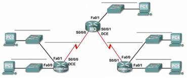
在本实验中,为您指定了一个网络地址 192.168.9.0/24,您将对它划分子网,并为拓扑图中显示的网络分配 IP 地址。路由器全部使用2621XM,交换机全部使用2960。
该网络的编址需求如下:
(1) BRANCH1 的 LAN 1 子网需要 10 个主机 IP 地址。
(2)BRANCH1 的 LAN 2 子网需要 10 个主机 IP 地址。
(3)BRANCH2 的 LAN 1 子网需要 10 个主机 IP 地址。
(4)BRANCH2 的 LAN 2 子网需要 10 个主机 IP 地址。
(5)HQ 的 LAN 子网需要 20 个主机 IP 地址。
(6)从 HQ 到 BRANCH1 的链路的两端各需要一个 IP 地址。
(7) 从 HQ 到 BRANCH2 的链路的两端各需要一个 IP 地址。
(注意:请记住,网络设备的接口也是主机 IP 地址,已包括在上面的编址需求中。)
1. 设计子网
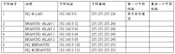
2. 分配IP地址(网关地址使用子网的第一个可用地址)
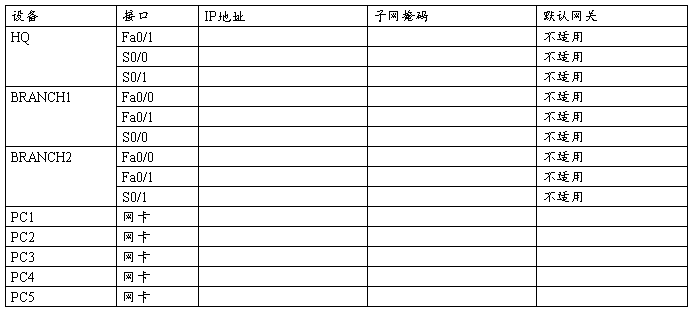
3. 连接网络(路由器之间使用DCE电缆连接到串行口)
4. 配置每台计算机的IP地址。
5. 配置路由器每个端口的IP地址
6. 设置路由器中的路由表。
路由表设置要求网络中每个子网之间都可以连通。
路由器配置详细操作
20##-11-13 15:48:27| 分类: 计算机网络原理|举报|字号 订阅
【BRANCH1的配置】
(1)关闭路由器电源
(2)安装模块WIT-2T。
(3)进入CLI
(4)进行以下操作(蓝色文字是需要输入的命令,红色文字是说明)
Continue with configuration dialog? [yes/no]: n
Press RETURN to get started!
进入控制台模式
Router>en
进入全局配置模式
Router#conf t
Enter configuration commands, one per line. End with CNTL/Z.
修改路由器名称
Router(config)#hostname BRANCH1
配置Fa0/0的IP地址
BRANCH1(config)#int f0/0
BRANCH1(config-if)#ip addr 192.168.9.33 255.255.255.240
BRANCH1(config-if)#no shutdown
%LINK-5-CHANGED: Interface FastEthernet0/0, changed state to up
%LINEPROTO-5-UPDOWN: Line protocol on Interface FastEthernet0/0, changed state to up
配置Fa0/1的IP地址
BRANCH1(config-if)#int f0/1
BRANCH1(config-if)#ip addr 192.168.9.49 255.255.255.240
BRANCH1(config-if)#no shutdown
%LINK-5-CHANGED: Interface FastEthernet0/1, changed state to up
%LINEPROTO-5-UPDOWN: Line protocol on Interface FastEthernet0/1, changed state to up
配置S0/0的IP地址。因为BRANCH1是BRANCH1和HQ之间串行通信的DCE设备,所以需要配置时钟频率。
BRANCH1(config-if)#int s0/0
BRANCH1(config-if)#ip addr 192.168.9.129 255.255.255.252
BRANCH1(config-if)#no shutdown
%LINK-5-CHANGED: Interface Serial0/0, changed state to up
BRANCH1(config-if)#clock rate 64000
%LINEPROTO-5-UPDOWN: Line protocol on Interface Serial0/0, changed state to up
返回到控制台模式。Exit命令返回到上一层,使用Ctrl+Z可以直接返回控制台。
BRANCH1(config-if)#exit
BRANCH1(config)#exit
%SYS-5-CONFIG_I: Configured from console by console
查看IP地址配置情况。
BRANCH1#show ip int bri
Interface IP-Address OK? Method Status Protocol
FastEthernet0/0 192.168.9.33 YES manual up up
FastEthernet0/1 192.168.9.49 YES manual up up
Serial0/0 192.168.9.129 YES manual up up
Serial0/1 unassigned YES manual administratively down down
添加路由表。这里没有使用路由总结。
BRANCH1#conf t
Enter configuration commands, one per line. End with CNTL/Z.
BRANCH1(config)#ip route 192.168.9.32 255.255.255.240 f0/0
BRANCH1(config)#ip route 192.168.9.48 255.255.255.240 f0/1
BRANCH1(config)#ip route 192.168.9.0 255.255.255.240 192.168.9.130
BRANCH1(config)#ip route 192.168.9.64 255.255.255.240 192.168.9.130
BRANCH1(config)#ip route 192.168.9.80 255.255.255.224 192.168.9.130
返回控制台
BRANCH1(config)#^Z
%SYS-5-CONFIG_I: Configured from console by console
查看路由表
BRANCH1#show ip route
Codes: C - connected, S - static, I - IGRP, R - RIP, M - mobile, B - BGP
D - EIGRP, EX - EIGRP external, O - OSPF, IA - OSPF inter area
N1 - OSPF NSSA external type 1, N2 - OSPF NSSA external type 2
E1 - OSPF external type 1, E2 - OSPF external type 2, E - EGP
i - IS-IS, L1 - IS-IS level-1, L2 - IS-IS level-2, ia - IS-IS inter area
* - candidate default, U - per-user static route, o - ODR
P - periodic downloaded static route
Gateway of last resort is not set
192.168.9.0/24 is variably subnetted, 6 subnets, 3 masks
S 192.168.9.0/28 [1/0] via 192.168.9.130
C 192.168.9.32/28 is directly connected, FastEthernet0/0
C 192.168.9.48/28 is directly connected, FastEthernet0/1
S 192.168.9.64/27 [1/0] via 192.168.9.130
S 192.168.9.64/28 [1/0] via 192.168.9.130
C 192.168.9.128/30 is directly connected, Serial0/0
【HQ的配置】
(1)关闭路由器电源
(2)安装模块WIT-2T。
(3)进入CLI
(4)进行以下操作(红色文字是说明)
Continue with configuration dialog? [yes/no]: n
Press RETURN to get started!
Router>en
Router#conf t
Enter configuration commands, one per line. End with CNTL/Z.
Router(config)#hostname HQ
HQ(config)#int f0/1
HQ(config-if)#ip addr 192.168.9.1 255.255.255.224
HQ(config-if)#no shutdown
%LINK-5-CHANGED: Interface FastEthernet0/1, changed state to up
%LINEPROTO-5-UPDOWN: Line protocol on Interface FastEthernet0/1, changed state to up
HQ(config-if)#int s0/0
HQ(config-if)#ip addr 192.168.9.130 255.255.255.252
HQ(config-if)#no shutdown
配置IP地址
%LINK-5-CHANGED: Interface Serial0/0, changed state to up
HQ(config-if)#
%LINEPROTO-5-UPDOWN: Line protocol on Interface Serial0/0, changed state to up
HQ(config-if)#int s0/1
HQ(config-if)#ip addr 192.168.9.134 255.255.255.252
HQ(config-if)#no shutdown
配置DCE设备的时钟频率。HQ是HQ和BRANCH2之间的DCE设备。
%LINK-5-CHANGED: Interface Serial0/1, changed state to up
HQ(config-if)#clock rate 64000
HQ(config-if)#
%LINEPROTO-5-UPDOWN: Line protocol on Interface Serial0/1, changed state to up
HQ(config-if)#^Z
%SYS-5-CONFIG_I: Configured from console by console
查看IP地址配置情况
HQ#show ip int bri
Interface IP-Address OK? Method Status Protocol
FastEthernet0/0 unassigned YES manual administratively down down
FastEthernet0/1 192.168.9.1 YES manual up up
Serial0/0 192.168.9.130 YES manual up up
Serial0/1 192.168.9.134 YES manual up up
添加路由表。这里使用了路由总结(请自行计算是如何总结的!),路由表从5条减少到3条。
HQ#conf t
Enter configuration commands, one per line. End with CNTL/Z.
HQ(config)#ip route 192.168.9.0 255.255.255.224 f0/1
HQ(config)#ip route 192.168.9.32 255.255.255.224 192.168.9.129
HQ(config)#ip route 192.168.9.64 255.255.255.192 192.168.9.133
HQ(config)#^Z
%SYS-5-CONFIG_I: Configured from console by console
HQ#show ip route
Codes: C - connected, S - static, I - IGRP, R - RIP, M - mobile, B - BGP
D - EIGRP, EX - EIGRP external, O - OSPF, IA - OSPF inter area
N1 - OSPF NSSA external type 1, N2 - OSPF NSSA external type 2
E1 - OSPF external type 1, E2 - OSPF external type 2, E - EGP
i - IS-IS, L1 - IS-IS level-1, L2 - IS-IS level-2, ia - IS-IS inter area
* - candidate default, U - per-user static route, o - ODR
P - periodic downloaded static route
Gateway of last resort is not set
192.168.9.0/24 is variably subnetted, 5 subnets, 3 masks
C 192.168.9.0/27 is directly connected, FastEthernet0/1
S 192.168.9.32/27 [1/0] via 192.168.9.129
S 192.168.9.64/26 [1/0] via 192.168.9.133
C 192.168.9.128/30 is directly connected, Serial0/0
C 192.168.9.132/30 is directly connected, Serial0/1
HQ#
【BRANCH2的配置】
(1)关闭路由器电源
(2)安装模块WIT-2T。
(3)进入CLI
(4)进行以下操作(红色文字是说明)
Continue with configuration dialog? [yes/no]: n
Press RETURN to get started!
Router>en
Router#conf t
Enter configuration commands, one per line. End with CNTL/Z.
Router(config)#hostname BRANCH2
配置每个端口的IP地址
BRANCH2(config)#int f0/0
BRANCH2(config-if)#ip addr 192.168.9.65 255.255.255.240
BRANCH2(config-if)#no shutdown
%LINK-5-CHANGED: Interface FastEthernet0/0, changed state to up
%LINEPROTO-5-UPDOWN: Line protocol on Interface FastEthernet0/0, changed state to up
BRANCH2(config-if)#int f0/1
BRANCH2(config-if)#ip addr 192.168.9.81 255.255.255.240
BRANCH2(config-if)#no shutdown
%LINK-5-CHANGED: Interface FastEthernet0/1, changed state to up
%LINEPROTO-5-UPDOWN: Line protocol on Interface FastEthernet0/1, changed state to up
BRANCH2(config-if)#int s0/1
BRANCH2(config-if)#ip addr 192.168.9.133 255.255.255.252
BRANCH2(config-if)#no shutdown
%LINK-5-CHANGED: Interface Serial0/1, changed state to up
BRANCH2(config-if)#
%LINEPROTO-5-UPDOWN: Line protocol on Interface Serial0/1, changed state to up
BRANCH2(config-if)#^Z
%SYS-5-CONFIG_I: Configured from console by console
BRANCH2#show ip int bri
Interface IP-Address OK? Method Status Protocol
FastEthernet0/0 192.168.9.65 YES manual up up
FastEthernet0/1 192.168.9.81 YES manual up up
Serial0/0 unassigned YES manual administratively down down
Serial0/1 192.168.9.133 YES manual up up
添加路由表
BRANCH2#conf t
Enter configuration commands, one per line. End with CNTL/Z.
BRANCH2(config)#ip route 192.168.9.64 255.255.255.240 f0/0
BRANCH2(config)#ip route 192.168.9.80 255.255.255.240 f0/1
BRANCH2(config)#ip route 192.168.9.0 255.255.255.192 192.168.9.134
BRANCH2(config)#^Z
%SYS-5-CONFIG_I: Configured from console by console
BRANCH2#show ip route
Codes: C - connected, S - static, I - IGRP, R - RIP, M - mobile, B - BGP
D - EIGRP, EX - EIGRP external, O - OSPF, IA - OSPF inter area
N1 - OSPF NSSA external type 1, N2 - OSPF NSSA external type 2
E1 - OSPF external type 1, E2 - OSPF external type 2, E - EGP
i - IS-IS, L1 - IS-IS level-1, L2 - IS-IS level-2, ia - IS-IS inter area
* - candidate default, U - per-user static route, o - ODR
P - periodic downloaded static route
Gateway of last resort is not set
192.168.9.0/24 is variably subnetted, 4 subnets, 3 masks
S 192.168.9.0/26 [1/0] via 192.168.9.134
C 192.168.9.64/28 is directly connected, FastEthernet0/0
C 192.168.9.80/28 is directly connected, FastEthernet0/1
C 192.168.9.132/30 is directly connected, Serial0/1
BRANCH2#
-
路由器基本配置实验报告
实验八路由器基本配置一实验目的掌握对路由器进行基本配置的方法二实验预习内容1路由器有哪两种管理方式答1带外管理通过交换机端口Con…
-
实验报告-路由器的基本配置
张强胜网络09120xx00824125实验一路由器的基本配置实验目的本次实验主要是学习几种路由器的工作模式间的关系及其如何利用超…
- 路由器的配置实验完整报告
-
静态路由配置实验报告
静态路由配置实验报告10网络王志龙20xx304020xx4一实验目的掌握路由器的基本使用及配置静态路由二实验内容1给各路由器命名…
-
路由器的基本配置实验报告
实验4路由器的基本配置1按照环境的要求建立实验的拓扑结构2配置六台主机的IP地址配置1988150网络中的两台主机的地址分别是19…
-
交换机路由器配置实验报告
实验一路由器基本配置时间20xx916实验目的掌握路由器基本配置实验重点配置主机名密码vty密码接口ip地址实验难点配置主机名密码…
-
路由器基本配置实验报告
实验八路由器基本配置一实验目的掌握对路由器进行基本配置的方法二实验预习内容1路由器有哪两种管理方式答1带外管理通过交换机端口Con…
-
静态路由配置实验报告
静态路由配置实验报告10网络王志龙20xx304020xx4一实验目的掌握路由器的基本使用及配置静态路由二实验内容1给各路由器命名…
- 路由器的配置实验完整报告
-
实验报告-路由器的基本配置
张强胜网络09120xx00824125实验一路由器的基本配置实验目的本次实验主要是学习几种路由器的工作模式间的关系及其如何利用超…
-
路由器配置实验报告
深圳大学实验报告课程名称学院实验时间实验报告提交时间教务处制方法步骤1标准静态路由的配置RouterA当前路由器提示视图ltRou…