菲涅耳双棱镜干涉实验指导书
实验五 菲涅耳双棱镜干涉
[实验目的]
1. 观察和研究菲涅耳双棱镜产生的干涉现象;
2. 测量干涉滤光片的透射波长(λ0)。
[仪器和装置]
白炽灯,干涉滤光片,可调狭缝,柱面镜,菲涅耳双棱镜,双胶合成像物镜,测微目镜。
[实验原理]
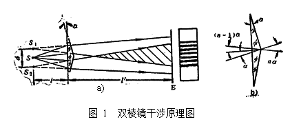
如图1a所示,菲涅耳双棱镜装置由两个相同的棱镜组成。两个棱镜的折射角a很小,一般约为5 ~ 30'。从点(或缝)光源S发出的一束光,经双棱镜折射后分为两束。从图中可以看出,这两折射光波如同从棱镜形成的两个虚像S1和S2发出的一样。S1和S2构成两相干光源,在两光波的迭加区产生干涉。
a
、
从图1b看出,若棱镜的折射率为n,则两虚像S1、S2之间的距离
 (5-1)
(5-1)
干涉条纹的间距
 (5-2)
(5-2)
式中,l为光波的波长。
对于玻璃材料的双棱镜有n=1.50,则
 (5-3)
(5-3)
可得到
 (5-4)
(5-4)
在迭加区内放置观察屏E,就可接收到平行于脊棱的等距直线条纹。若用白光照明,可接收到彩色条纹。
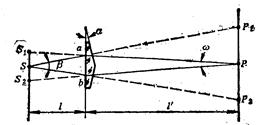
对于扩展光源,由图2可导出干涉孔径角:
 (5-5)
(5-5)
和光源临界宽度:
 (5-6)
(5-6)
从式(5-5)和(5-6)看出,当l'=0时,β=0,则光源的临界宽度b变为无穷大。此时,干涉条纹定域在双棱镜的脊棱附近。b为有限值时,条纹定域在以下区域内:
 (5-7)
(5-7)

[内容和步骤]
1.调整光路,观察和研究双棱镜干涉现象
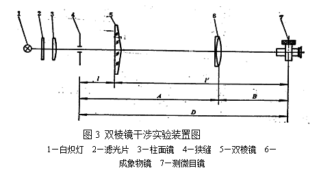
(1) 按图3所示,将光学元件置于光学平台上。调整光学元件,使其满足同轴等高的要求。
(2) 取l≈200mm,l'≈1200mm,按λ=550nm,a=30',n=1.50计算出b的数值。置狭缝宽度bt=b/4,调节棱镜的脊棱与狭缝方向平行,直到使得测微目镜视场里出现清晰的干涉条纹为止。增大或减小狭缝宽度,观察干涉条纹对比度的变化,并给予解释。
2.测量干涉滤光片中心透射长λ0。
由式(5-3)看出,为了测量λ0,需要在一定的精度范围测定d、l、l'与e值。
(1) 测定d值
如图4所示,通常S1、S2和S并不在与图面垂直的同一平面内,而D和A又应从S1S2处测量才算准确。故测量d时,采用二次(共轭)成像法,即保持物像位置不变,移动成像物镜。当成像物镜6在第一个位置时,若从测微目镜中测得S1,S2的两个实像 ,
, 之间的距离d1,据物像关系,则有
 (5-8)
(5-8)
物镜6在第二个(共轭)位置成像时,则有
 (5-9)
(5-9)
由上两式可解出
 (5-10)
实验时,对d值的测量不应少于三次,然后取其平均值 。
。

(2) D的计算
设物镜6从第一个位置移置至第二个(共轭)位置的位移量是C,则C=B-A,而D=l+l'=A+B,再与式(5-9)和(5-10)联立,消去A、B,可得到:
 (5-11)
由各次测量C、d1、d2的值,计算相应的D,然后取其平均值 。
。
(3) 测量条纹间距e
用测微目镜测出10条以上明(或暗)条纹的宽度,计算出干涉条纹间距e。多次重复测量,取其平均值 。
。
 (4) 将
(4) 将 各值代入式(5-4)计算干涉滤光片中心透射波长λ0。
[思考题]
如果狭缝方向与脊棱稍不平行,就观察不到干涉条纹,为什么?
Experiment 5 Use of Fresnel's biprism to determine transmission wavelength of an interferometric filter
[Experimental Objectives]
1. To observe and study the interference phenomenon by using a Fresnel's biprism
2. To determine the transmission wavelength (l0) of an interferometric filter
[Apparatus and Setup]
Incandescent lamp, interferometric filter, adjustable slit, cylindrical lens, Fresnel's biprism, doublet imaging objective, and micrometer eyepiece
[Experimental Principle]
As shown in Fig. 1a, the Fresnel's biprism system consists of two identical prisms (biprism), whose refractive angles are very small (normally ca 5 ~ 30¢). Refracted by the biprism, a beam from a point (or slit) light source is split into two. It can be seen from Fig. 1a that two refracted beams seem to come from two virtual images, S1 and S2. Here S1 and S2 are coherent light sources, which may produce interference patterns in the overlapped region of two beams.
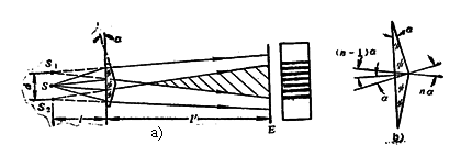
Fig. 1 Principle of Fresnel's biprism interference
From Fig. 1b, if the refractive index of the prism is n, the separation of two virtual images S1 and S2 can be expressed as: (5-1)
and the separation of two fringes is given by
(5-2)
where l is the light wavelength.
Given n=1.50, we have
(5-3)
or
. (5-4)
A screen E is placed in the overlapped region and some equi-spaced straight fringes, which are parallel to the prism spine, are produced. If an incandescent lamp is used as the light source, chromatic fringes can be observed.
Based on Fig. 2, the interference aperture angle can be derived as
(5-5)
and the critical width of the light source is
 . (5-6)
Fig. 2 Geometrical relationship of Fresnel's biprism interference
From Eqs. (5-5) and (5-6), if l'=0, β=0, resulting in the critical width of the light source (b) being infinite. In this case, interference fringes are produced near the biprism spine. If b is of a finite value, fringe localization is in the following region:
. (5-7)
[Experimental Procedure]
1. Adjust light path to observe biprism interference phenomenon
(1) The optical apparatus are arranged on an optical bench as shown schematically in Fig. 3. Adjust the optical elements in order to meet the requirements of proper alignment and equal height.

Fig. 3 Setup of Fresnel's biprism interference
1-Incandescent lamp 2-Interferometric filter 3-Cylindrical lens 4-Adjustable slit 5-Fresnel's biprism 6-Objective 7-Micrometer eyepiece
(2) Assuming  ≈200mm and
  ≈1200mm, for λ=550nm, a=30', and n=1.50, the value of b can be calculated. Set the slit width bt=b/4, and adjust the prism spine parallel to the slit until clear interference fringes appear in the microscope field. Increase or decrease the slit width, see what will happen to the contrast of interference fringes and give your explanations.
2. Determine the transmission wavelength (l0) of an interferometric filter
From Eq. (5-3), in order to determine λ0, it is necessary to measure the values of d, l, l', and e with relatively high accuracies.
(1) Determination of d
As shown in Fig. 4, S1, S2 and S are usually not in the same plane perpendicular to the paper. However, D and A only can be measured accurately from the S1S2 position. Therefore, secondary (conjugate) imaging will be used for the determination of d. When the objective 6 is at the first position, if the distance d1 of two real images and of S1 and S2 is measured by the micrometer eyepiece, based on the relationship of objective and image, the following expression can be obtained:
. (5-8)
While the objective is at the second (conjugate) position, we have
. (5-9)
From the above two equations,
. (5-10)
In this experiment, d is measured no less than three times and the average value is calculated.

Fig. 4 Determination of d by secondary (conjugate) imaging
(2) Calculation of D
If the displacement of the objective 6 between the first position and the second (conjugate) position is C, C=B-A and D=l+l'=A+B. Combined with Eqs. (5-9) and (5-10), we have:
. (5-11)
From the values of C, d1 and d2, the corresponding D value can be calculated and the average value is obtained.
(3) Measurement of fringe separation e
Measure the widths of more than 10 bright (or dark) fringes using the micrometer eyepiece and calculate the fringe separation e. Repeat the measurement for several times and calculate their average value .
(4) Substitute the values of , and into Eq. (1-4) to calculate the central transmission wavelength (l0) of the interferometric filter.
[Questions]
If the slit is oriented slightly unparallel to the prism spine, interference fringes cannot be observed. Why?
-
菲涅尔干涉实验报告
菲涅尔干涉测钠光波长【实验目的】(1)观察双棱镜干涉现象,测量钠光的波长。(2)学习和巩固光路的同轴调整。(3)通过观察双棱镜产生…
-
菲涅尔双棱镜干涉实验
实验报告实验题目菲涅尔双棱镜干涉实验系别物理与电子科学系专业物理学班级20xx级物理学班姓名张凤兴学号2010051035老师冉老…
-
研究性报告-菲涅尔双棱镜干涉实验的改进及误差分析
大学物理实验研究性报告菲涅尔双棱镜干涉实验的改进及误差分析作者:北京航空航天大学20##.12.12摘要本文通过对菲涅尔双棱镜干涉…
-
北航基础物理实验研究性报告 菲涅耳双棱镜干涉实验的改进
基础物理实验研究性报告菲涅耳双棱镜干涉实验的改进第一作者第二作者所在院系攻读专业20##年12月18日摘要在进行菲涅耳双棱镜干涉实…
-
菲涅尔双棱镜实验
菲涅尔双棱镜干涉物理研究性报告菲涅尔双棱镜干涉1菲涅尔双棱镜干涉摘要当两束光波的频率相同振动方向相同且相位差恒定时可以产生干涉本实…
-
菲涅尔双棱镜干涉实验
实验报告实验题目菲涅尔双棱镜干涉实验系别物理与电子科学系专业物理学班级20xx级物理学班姓名张凤兴学号2010051035老师冉老…
-
研究性报告-菲涅尔双棱镜干涉实验的改进及误差分析
大学物理实验研究性报告菲涅尔双棱镜干涉实验的改进及误差分析作者:北京航空航天大学20##.12.12摘要本文通过对菲涅尔双棱镜干涉…
-
菲涅尔双棱镜实验
菲涅尔双棱镜干涉物理研究性报告菲涅尔双棱镜干涉1菲涅尔双棱镜干涉摘要当两束光波的频率相同振动方向相同且相位差恒定时可以产生干涉本实…
-
关于菲涅耳双棱镜实验的再思考
关于菲涅耳双棱镜实验的再思考崔忱高等工程学院13071141摘要本文利用物理上的几何光学方法对于菲涅耳双棱镜的干涉进行了理论推导并…