接口实验报告

现代微机原理与接口技术
(接口部分)
实验报告
学号: 09008112 姓名: 马京亚 成绩:
学号: 09008123 姓名: 郭晨 成绩:
东南大学计算机科学与工程学院
二〇##年十二月
目录
实验二 可编程定时器计数器8253. 3
实验三 Windows中断... 5
实验四 8255实验... 9
实验五 七段数码管实验... 13
实验六 竞赛抢答器... 20
实验七 交通灯控制实验... 22
实验二 可编程定时器计数器8253
1、实验目的
掌握8253的基本原理和编程方法
2、实验内容
实验(1)
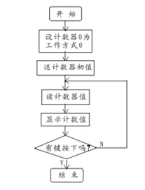
将8253计数器0设置为方式0,计数器初值设置为N(N≤0FH)。将实验台上单脉冲接到CLK0 上,用手动逐个输入单脉冲,编程使计数值在计算机屏幕上显示(查询方式),并同时用逻辑笔观察OUT0电平变化(当输入N+1个脉冲后OUT0变高电平)。
流程图
接线说明
8253:CS# --> 280H-287H
CLK0 --> 单脉冲
GATE0 --> VCC
OUT0 --> 逻辑笔
程序
//Lab2_1
#include <stdio.h>
#include <conio.h>
#include "ApiEx.h"
#pragma comment (lib,"ApiEx.lib")
void main()
{
printf("Press any key to begin!\n");
getch();
printf("Press any key to exit!\n");
if(!Startup())
{
printf("ERROR:Open Device Error!\n");
return;
}
unsigned char data;
PortWriteByte(0x283,0x10);
PortWriteByte(0x280,10);
while(!kbhit())
{
PortReadByte(0x280,&data);
printf("%d\n",data);
Sleep(1000);
}
Cleanup();
}
实验(2)
将计数器0,计数器1分别设置为方式3,利用这两个计数器,将实验台上的一个1MHz的方波信号分频为1Hz的方波(做好8253初始化工作),并将此方波接到L7上,观察L7以周期为1秒的频率闪烁。
接线说明
8253:CS# --> 280H-287H
CLK0 --> 1MHz
OUT0 --> CLK1
GATE0 --> VCC
GATE1 --> VCC
OUT1 --> L7
程序
//Lab2_2
#include <stdio.h>
#include <conio.h>
#include "ApiEx.h"
#pragma comment (lib,"ApiEx.lib")
void main()
{
printf("Press any key to begin!\n");
getch();
printf("Press any key to exit!\n");
if(!Startup())
{
printf("ERROR:Open Device Error!\n");
return;
}
PortWriteByte(0x283, 0x37);
PortWriteByte(0x283, 0x77);
PortWriteByte(0x280, 0x00);
PortWriteByte(0x280, 0x10);
PortWriteByte(0x281, 0x00);
PortWriteByte(0x281, 0x10);
while (!kbhit()) {}
}
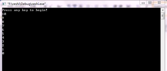
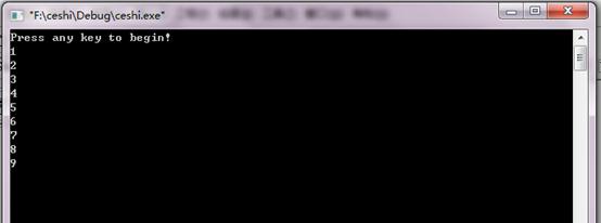
3、实验结果
实验(1)
用手动逐个输入单脉冲,编程使计数值在计算机屏幕上显示,当输入N+1个脉冲后OUT0变高电平。
实验(2)
l7以周期1秒闪烁
实验三 Windows中断
1、实验目的
了解Windows下中断处理过程
比较中断和查询两种数据交换方法的效率差别。
2、实验内容
实验(1)
用查询和中断方式分别实现控制指示灯,然后在任务栏中比较中断和查询方式下CPU利用率的差别
查询方式
将8255的A口设为输出,接指示灯L0~L7,C口设为输入并将PC0接正脉冲输入,CS接到实验台的138译码的8组I/O地址中的任意一组上,通过程序不断地查询PC0的输入值, 当为高电平的时候让指示灯显示一秒钟的0x55(软件延时),否则让指示灯显示0xAA。
接线说明
8255:CS# --> 280H-287H
PC0 --> 单脉冲
PA0-PA7 --> L0-L7
程序
//Lab3_1_1
#include <stdio.h>
#include <conio.h>
#include "ApiEx.h"
#pragma comment(lib,"ApiEx.lib")
void main()
{
printf("Press any key to begin!\n");
getch();
printf("Press any key to exit!\n");
if(!Startup())
{
printf("ERROR:Open Device Error!\n");
return;
}
PortWriteByte(0x283, 0x89);
while (!kbhit()) {
PortReadByte(0x282,&data);
if (data&0x01) {
PortWriteByte(0x280,0x55);
Sleep(1000);
}
else {
PortWriteByte(0x280,0xAA);
Sleep(1000);
}
}
Cleanup();
}
中断方式
将8255的A口设为输出,接指示灯L0~L7,CS接到实验台的138译码的8组I/O地址中的任意一组上,IRQ直接接到实验台上的单脉冲,要求直接用手动产生的单脉冲作为中断请求信号,每按一次单脉冲产生一次中断让指示灯显示一秒钟的0x55,否则让指示灯显示0xAA。
接线说明
8255:CS# --> 280H-287H
IRQ --> 单脉冲
PA0-PA7 --> L0-L7
程序
Lab3_1_2
#include <stdio.h>
#include <conio.h>
#include "ApiEx.h"
#pragma comment(lib,"ApiEx.lib")
int i;
void MyISR()
{
PortWriteByte(0x288,0x55);
Sleep(1000);
printf("%d\n",i++);
}
void main()
{
printf("Press any key to begin!\n");
getch();
if(!Startup())
{
printf("ERROR:Open Device Error!\n");
return;
}
printf("Press any key to exit!\n");
PortWriteByte(0x28b, 0xa0);
RegisterLocalISR(MyISR);
EnableIntr();
while (!kbhit()) {
PortWriteByte(0x288,0xaa);
Sleep(100);
}
DisableIntr();
Cleanup();
}
实验(2)
利用实验二的第二个实验产生一个周期为1秒的中断,编程在中断处理程序中打印中断的 次数到计算机屏幕上。
接线说明
8255:CS# --> 288H-28FH
IRQ --> OUT1
8253:CS# --> 280H-287H
CLK0 --> 1MHz
OUT0 --> CLK1
GATE0 --> VCC
GATE1 --> VCC
程序
//Lab3_2
#include <stdio.h>
#include <conio.h>
#include "ApiEx.h"
#pragma comment (lib,"ApiEx.lib")
int i=0;
void MyISR(){
printf("%d\n",i++);
}
void main()
{
printf("Press any key to begin!\n");
getch();
if(!Startup())
{
printf("ERROR:Open Device Error!\n");
return;
}
printf("Press any key to exit!\n");
PortWriteByte(0x28b,0x80);
PortWriteByte(0x283, 0x37);
PortWriteByte(0x283, 0x77);
PortWriteByte(0x280, 0x00);
PortWriteByte(0x280, 0x10);
PortWriteByte(0x281, 0x00);
PortWriteByte(0x281, 0x10);
RegisterLocalISR(MyISR);
EnableIntr();
while(!kbhit()) {}
DisableIntr();
Cleanup();
}
3、实验结果
实验(1):
查询方式时,当有单脉冲输入的时候,PC0变为高电平,指示灯显示1s的0x55,否则显示0xAA。观察到CPU使用率为100%。
中断方式:当有单脉冲输入的时候,产生一次中断,指示灯显示1s的0x55,否则显示0xAA。观察到CPU使用率为2%。
由以上对比可知,中断方式比查询方式效率要高很多。因为如果使用查询方式,系统连续不断地运行查询程序;而在中断方式中,只有在中断到来时系统才运行中断服务程序,其余时间系统是空闲的。
实验(2):
实验四 8255实验
1、实验目的
掌握8255方式0和方式1的工作原理及使用方法,进一步掌握中断处理程序的编写。
2、实验内容
实验(1)
8255的C口接逻辑电平开关K0~K7,A口接LED显示电路L0~L7,CS接到实验台的138译码的8组I/O地址中的任意一组上,编程采用查询方式从8255C口输入数据再从A口输出。
接线说明
8255:CS# --> 280H-287H
PC0-PC7 --> K0-K7
PA0-PA7 --> L0-L7
程序
//Lab4_1
#include <stdio.h>
#include <conio.h>
#include "ApiEx.h"
#pragma comment(lib,"ApiEx.lib")
void main()
{
printf("Press any key to begin!\n\n");
getch();
printf("Press any key to exit!\n");
if(!Startup())
{
printf("ERROR:Open Device Error!\n");
return;
}
PortWriteByte(0x283, 0x89);
unsigned char data;
while(!kbhit())
{
PortReadByte(0x282, &data);
PortWriteByte(0x280, data);
}
Cleanup();
}
实验(2)
将8255的A口设置为方式1输入,接LED显示电路L0~L7。将单脉冲接到8255的PC6上,每按一次单脉冲按钮产生一个脉冲,该脉冲使8255通过PC3产生一次中断请求道IRQ。CS接到试验台的138译码的8组I/O地址中的任意一组上,编程在中断处理程序中一次输出01H、02H、04H、08H、10H、20H、40H、80H,使L0~L7依次发光,中断8次结束。
接线说明
8255:CS# --> 280H-287H
PA0-PA7 --> L0-L7
PC3 --> IRQ
PC6 --> 单脉冲
程序
//Lab4_2
#include <stdio.h>
#include <conio.h>
#include "ApiEx.h"
#pragma comment(lib,"ApiEx.lib")
unsigned char data;
int i = -1;
void MyISR()
{
i++;
BYTE data[8]={0x01,0x02,0x04,0x08,0x10,0x20,0x40,0x80};
PortWriteByte(0x280,data[i]);
printf("%d", data[i]);
}
void main()
{
printf("Press any key to begin!\n\n");
getch();
printf("Press any key to exit!\n");
if(!Startup())
{
printf("ERROR:Open Device Error!\n");
return;
}
PortWriteByte(0x283, 0xb0);
PortWriteByte(0x283, 0x09);
RegisterLocalISR(MyISR);
EnableIntr();
while(!kbhit())
{
if (i == 8) {
break;
}
}
DisableIntr();
Cleanup();
}
实验(3)
将8255的A口设置为方式1输入,接逻辑电平开关K0~K7。将单脉冲接到8255的PC4上,每按一次单脉冲按钮产生一个脉冲,该脉冲使8255通过PC3产生一次中断请求到IRQ。CS接到实验台的138译码的8组I/O地址中的任意一组上,编程在中断处理程序中读取逻辑电平开关预置的ASCII码,在屏幕上现实其对应的字符,中断8次结束。
接线说明
8255:CS# --> 280H-287H
PA0-PA7 --> K0-K7
PC3 --> IRQ
PC4 --> 单脉冲
程序
//Lab4_3
#include <stdio.h>
#include <conio.h>
#include "ApiEx.h"
#pragma comment(lib,"ApiEx.lib")
unsigned char data;
int i = 0;
void MyISR()
{
i++;
PortReadByte(0x280,&data);
printf("%c", data);
}
void main()
{
printf("Press any key to begin!\n\n");
getch();
printf("Press any key to exit!\n");
if(!Startup())
{
printf("ERROR:Open Device Error!\n");
return;
}
PortWriteByte(0x283, 0xb0);
PortWriteByte(0x283, 0x09);
RegisterLocalISR(MyISR);
EnableIntr();
while(!kbhit())
{
if (i == 8) {
break;
}
}
DisableIntr();
Cleanup();
}
3、实验结果
实验(1)
开关K0-K7控制LED显示电路显示数字
实验(2)
依次输出01H,02H,04H,08H,10H,20H,40H,80H,L0-L7依次发光
实验(3)
电脑中显示K0-K7对应的ASC码
实验五 七段数码管实验
1、实验目的
掌握数码管显示数字的原理。
2、实验内容
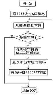
实验(1)
静态显示:将8255的A口PA0~PA6分别与七段数码管的段码驱动输入端a~g相连(方式0),位码驱动输入端S1接+5V(选中),S0、dp接地(关闭)。编程从PC键盘输入一位十进制数字0~9,在七段数码管上显示出来。
接线说明
8255:CS# --> 280H-287H
PA0-PA6 --> a-g
S1 --> VCC
S0 --> GND
dq --> GND
程序
//Lab5_1
#include <stdio.h>
#include <conio.h>
#include "ApiEx.h"
#pragma comment(lib,"ApiEx.lib")
void main()
{
printf("Press any key to begin!\n\n");
getch();
printf("Begin! \n");
if(!Startup())
{
printf("ERROR:Open Device Error!\n");
return;
}
PortWriteByte(0x283, 0x80);
unsigned char data = '0';
while(true)
{
data = getch();
if (data == '0') {
PortWriteByte(0x280, 0x3f);
}
if (data == '1') {
PortWriteByte(0x280, 0x06);
}
if (data == '2') {
PortWriteByte(0x280, 0x5b);
}
if (data == '3') {
PortWriteByte(0x280, 0x4f);
}
if (data == '4') {
PortWriteByte(0x280, 0x66);
}
if (data == '5') {
PortWriteByte(0x280, 0x6d);
}
if (data == '6') {
PortWriteByte(0x280, 0x7d);
}
if (data == '7') {
PortWriteByte(0x280, 0x07);
}
if (data == '8') {
PortWriteByte(0x280, 0x7f);
}
if (data == '9') {
PortWriteByte(0x280, 0x6f);
}
}
Cleanup();
}
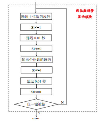
实验(2)
动态显示:七段数码管段码连接不变,位码驱动输入端S1、S0接8255 C口的PC1、PC0。编程在两个数码管上循环显示00-99。
流程图
接线说明
8255:CS# --> 280H-287H
PA0-PA6 --> a-g
PC1 --> S1
PC0 --> S0
dq --> GND
程序
//Lab5_2
#include <stdio.h>
#include <conio.h>
#include "ApiEx.h"
#pragma comment(lib,"ApiEx.lib")
void main()
{
printf("Press any key to begin!\n\n");
getch();
printf("Press any key to exit!\n");
if(!Startup())
{
printf("ERROR:Open Device Error!\n");
return;
}
PortWriteByte(0x283, 0x80);
int i = 0;
unsigned char shiweidata = 0x3f;
unsigned char geweidata = 0x3f;
while(!kbhit())
{
if (i == 100)
i = 0;
int shiwei = i/10;
int gewei = i%10;
switc(shiwei)
{
case 0:shiweidata = 0x3f; break;
case 1:shiweidata = 0x06; break;
case 1:shiweidata = 0x5b; break;
case 1:shiweidata = 0x4f; break;
case 1:shiweidata = 0x66; break;
case 1:shiweidata = 0x6d; break;
case 1:shiweidata = 0x7d; break;
case 1:shiweidata = 0x07; break;
case 1:shiweidata = 0x7f; break;
case 1:shiweidata = 0x6f; break;
}
switc(gewei)
{
case 0:geweidata = 0x3f; break;
case 1: geweidata = 0x06; break;
case 1: geweidata = 0x5b; break;
case 1: geweidata = 0x4f; break;
case 1: geweidata = 0x66; break;
case 1: geweidata = 0x6d; break;
case 1: geweidata = 0x7d; break;
case 1: geweidata = 0x07; break;
case 1: geweidata = 0x7f; break;
case 1: geweidata = 0x6f; break;
}
i++;
PortWriteByte(0x280, shiweidata);
PortWriteByte(0x283, 0x03);
Sleep(10);
PortWriteByte(0x283, 0x02);
PortWriteByte(0x280, geweidata);
PortWriteByte(0x283, 0x01);
Sleep(10);
PortWriteByte(0x283, 0x00);
}
Cleanup();
}
实验(3)
中断显示,将8255的A口设置成方式1输出,连接七段数码管的断码驱动输入端a~g,数码管位码驱动输入端S1接+5V(选中),S0、dp接地(关闭)。8255的C口下半部分设置为输入方式,PC0、PC1、PC2分别接逻辑电平开关K0~K2,单脉冲接到8255的PC6上,通过8255的PC3发中断,中断处理程序读取PC0~PC2,根据输入的值,在数码管中输出0~7
接线说明
8255:CS# --> 280H-287H
PA0-PA6 --> a-g
S1 --> VCC
S0 --> GND
dp -->GND
PC0~2 --> K0~2
PC3 --> IRQ
PC6 --> 单脉冲
程序
//Lab5_3
#include <stdio.h>
#include <conio.h>
#include "ApiEx.h"
#pragma comment(lib,"ApiEx.lib")
DWORD address0 = 0x280;
DWORD address1 = 0x281;
DWORD address2 = 0x282;
DWORD address3 = 0x283;
BYTE data;
int num;
void show(int i)
{
switch(i)
{
case 0:
PortWriteByte(address0,0x3F);
Sleep(100);
break;
case 1:
PortWriteByte(address0,0x06);
Sleep(100);
break;
case 2:
PortWriteByte(address0,0x5B);
Sleep(100);
break;
case 3:
PortWriteByte(address0,0x4F);
Sleep(100);
break;
case 4:
PortWriteByte(address0,0x66);
Sleep(100);
break;
case 5:
PortWriteByte(address0,0x6D);
Sleep(100);
break;
case 6:
PortWriteByte(address0,0x7D);
Sleep(100);
break;
case 7:
PortWriteByte(address0,0x07);
Sleep(100);
break;
case 8:
PortWriteByte(address0,0x7F);
Sleep(100);
break;
case 9:
PortWriteByte(address0,0x6F);
Sleep(100);
break;
default:
break;
}
}
void MyISR()
{
PortReadByte(address2,&data);
Sleep(100);
num=data & 7;
show(num);
}
void main()
{
printf("Press any key to begin!\n\n");
getch();
if(!Startup())
{
printf("ERROR: Open Device Error!\n");
return;
}
printf("Press any key to exit!\n");
PortWriteByte(address3,0xA1);
Sleep(100);
PortWriteByte(address3,0x0D);
Sleep(100);
RegisterLocalISR(MyISR);
EnableIntr();
while(!kbhit())
{
Sleep(100);
}
DisableIntr();
Cleanup();
}
3、实验结果
实验(1)
键盘输入数字在数码管中显示
实验(2)
数码管上开始从00-99计数,循环
实验(3)
K0-K2的二进制数控制数码管显示对应的数字
实验六 竞赛抢答器
1、实验目的
了解微机化竞赛抢答器的基本原理
进一步学习使用并行接口
2、实验内容
设置8255为方式0下的C口输入,按逻辑电平开关K0~K7,A口输出,按数码管的段嘛驱动输入端a~g。读取C口数据,若为0表示无人抢答,若不为0则有人抢答。根据读取数据可判断其组号,在七段数码管上将其组号0-7显示出来。从键盘上按空格键开始下一轮抢答,按其他键程序退出。
//Lab6
#include<stdio.h>
#include<conio.h>
#include "ApiEx.h"
#pragma comment(lib,"ApiEx.lib")
int led[9]={0x3f,0x06,0x5b,0x4f,0x66,0x6d,0x7d,0x07,0x7f};
int num[8]={0x01,0x02,0x04,0x08,0x10,0x20,0x40,0x80};
int i=0;
void main()
{
BYTE data;
if(!Startup())
{
printf("ERROR: Open Device Error!\n");
return;
}
printf("ESC is to exit!");
PortWriteByte(0x28b,0x89);
for(;;)
{
if(getch() == 32)
PortWriteByte(0x288,led[0]);
do{
PortReadByte(0x28a,&data);
}
while(!data);
for(i=0;i<9;i++)
{
if(data==num[i])
{
printf("\7");
break;
}
}
if(i<9)
{
PortWriteByte(0x288,led[i+1]);
data=0;
}
if(getch() == 27)
exit(0);
PortWriteByte(0x288,0);
}
Cleanup();
}
3、实验结果
以空格键作为开始信号,显示第一个抢答的组号,以空格键重置。
实验七 交通灯控制实验
1、实验目的
通过并行接口8255实现十字路口交通灯的模拟控制,进一步掌握对并行口的使用和中断的使用。
2、实验内容
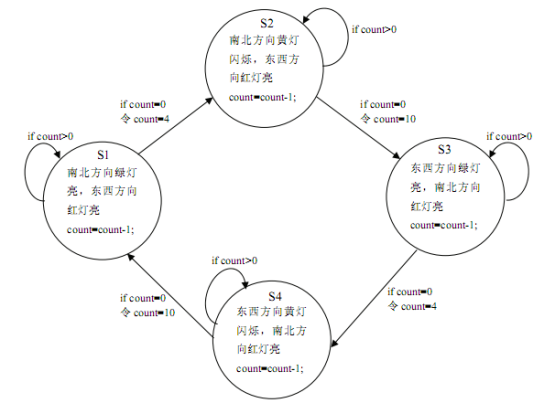
实验(1)
带倒计时的交通灯控制:将L7、L6、L5作为南北路口的交通灯与PC7、PC6、PC5相连;L2、L1、L0作为东西路口的交通灯与PC2、PC1、PC0相连(方式0)。PA口的PA0~PA6作为输出口(方式0输出)连接7段数码管的段码,PC3、PC4连接数码管的S0,S1来选择显示的位。利用8253产生1秒的中断信号,在中断处理程序中用程序处理10秒延迟和三次黄灯闪烁的问题。
编程使六个灯按交通灯变化规律燃灭,同时数码管显示倒计时的值(10~0,4~0)。
状态转化图
接线说明
8253:CS# --> 288H-28FH
CLK0 --> 1MHz
OUT0 --> CLK1
OUT --> IRQ
GATE0 --> VCC
GATE1 --> VCC
8255:CS# --> 280H-287H
PC0~7 --> L0~7
PA0-PA6 --> a-g
S1 --> PC4
S0 --> PC3
dq --> GND
程序
//lab7_1
#include <stdio.h>
#include <conio.h>
#include "ApiEx.h"
#pragma comment(lib,"ApiEx.lib")
unsigned char data;
int count=10;
int state=1;
void show(int i) {
if (i==10) {
for(int j=0;j<30;j++) {
PortReadByte(0x282,&data);
data=data&0xE7;
data=data|0x10;
PortWriteByte(0x280,0x06);
PortWriteByte(0x282,data);
Sleep(10);
data=data&0xE7;
data=data|0x08;
PortWriteByte(0x280,0x3F);
PortWriteByte(0x282,data);
Sleep(10);
}
}
else
switch(i)
{
case 0: PortWriteByte(0x280,0x3F);
break;
case 1: PortWriteByte(0x280,0x06);
if (state==2){
PortWriteByte(0x282,0x0C);
}
if (state==4){
PortWriteByte(0x282,0x88);
}
break;
case 2: PortWriteByte(0x280,0x5B);
if (state==2){
PortWriteByte(0x282,0x4C);
}
if (state==4){
PortWriteByte(0x282,0x8A);
}
break;
case 3: PortWriteByte(0x280,0x4F);
if (state==2){
PortWriteByte(0x282,0x0C);
}
if (state==4){
PortWriteByte(0x282,0x88);
}
break;
case 4: PortWriteByte0x280,0x66);
break;
case 5: PortWriteByte(0x280,0x6D);
break;
case 6: PortWriteByte(0x280,0x7D);
break;
case 7: PortWriteByte(0x280,0x07);
break;
case 8: PortWriteByte(0x280,0x7F);
break;
case 9: PortWriteByte(0x280,0x6F);
break;
default: break;
}
}
void MyISR() {
if(count>1){
count--;
show(count);
}
else
switch(state)
{
case 1: PortWriteByte(0x282,0x4C);
count=4;
state=2;
show(count);
break;
case 2: PortWriteByte(0x282,0x89);
count=10;
state=3;
show(count);
break;
case 3: PortWriteByte(0x282,0x8A);
count=4;
state=4;
show(count);
break;
case 4: PortWriteByte(0x282,0x2C);
count=10;
state=1;
show(count);
break;
default: break;
}
}
void main()
{
printf("Press any key to begin!\n\n");
getch();
printf("Press any key to exit!\n");
if(!Startup())
{
printf("ERROR:Open Device Error!\n");
return;
}
PortWriteByte(0x28b,0x37);
PortWriteByte(0x288,0);
PortWriteByte(0x288,10);
PortWriteByte(0x28b,0x77);
PortWriteByte(0x289,0);
PortWriteByte(0x289,10);
PortWriteByte(0x283,0x80);
PortWriteByte(0x280,0x80);
PortWriteByte(0x282,0x2C);
RegisterLocalISR(MyISR);
EnableIntr();
while(!kbhit()) {}
DisableIntr();
Cleanup();
}
实验(2)
带违章拍照功能的交通灯控制:将L7、L6、L5作为南北路口的交通灯与PA7、PA6、PA5
相连;L2、L1、L0作为东西路口的交通灯与PA2、PA1、PA0相连。PA口工作在方式1(输
出)。利用8253产生1秒的中断信号,在中断处理程序中用程序处理10秒延迟和三次黄灯闪烁的问题。利用单脉冲信号连接到PC6,作为信号输入,由8255产生中断(模拟东西方向上的汽车压黄线),该中断处理程序在东西方向为红灯的时候,令L3灯闪烁一下(周期100ms秒,利用软件延迟,用PA3控制)。编程使六个灯按交通灯变化规律燃灭,同时处理东西方向汽车压黄线问题。
接线说明
8253:CS# --> 288H-28FH
CLK0 --> 1MHz
OUT0 --> CLK1
CLK1 --> OUT0
OUT1 --> IRQ
GATE0 --> VCC
GATE1 --> VCC
8255:CS# --> 280H-287H
PA7 --> L7
PA6 --> L6
PA5 --> L5
PA3 --> L3
PA2 --> L2
PA1 --> L1
PA0 --> L0
PC3 --> IRQ
PC6 --> 单脉冲
D触发器:
C --> PC1
Q --> PC4
S --> PC3#
程序
//lab7_2
#include <stdio.h>
#include <conio.h>
#include "ApiEx.h"
#pragma comment(lib,"ApiEx.lib")
DWORD address0 = 0x280; //8255
DWORD address1 = 0x288; //8253
unsigned char data;
int count=10;
int state=1;
void MyISR_8253() {
if(count>1){
count--;
if (ccount==1){
if (state==2){
PortWriteByte(0x280,0x04);
}
if (state==4){
PortWriteByte(0x280,0x80);
}
}
if (count==2){
if (state==2){
PortWriteByte(0x280,0x44);
}
if (state==4){
PortWriteByte(0x280,0x82);
}
}
if (count==3){
if (state==2){
PortWriteByte(0x280,0x04);
}
if (state==4){
PortWriteByte(0x280,0x80);
}
}
}
else
{
switch(state)
{
case 1: PortWriteByte(0x280,0x44);
count=4;
state=2;
break;
case 2: PortWriteByte(0x280,0x81);
count=10;
state=3;
break;
case 3: PortWriteByte(0x280,0x82);
count=4;
state=4;
break;
case 4: PortWriteByte(0x280,0x24);
count=10;
state=1;
break;
default:
break;
}
}
}
void MyISR_8255()
{
if (state==2||state==1){
PortReadByte(0x280,&data);
PortWriteByte(0x280,data|0x08);
Sleep(100);
PortWriteByte(0x280,data);
}
}
void MyISR()
{
PortReadByte(0x282,&data);
data=data&0x10;
if (data==0x00) MyISR_8253();
else {
MyISR_8255();
PortWriteByte(0x283,0x02);
Sleep(100);
PortWriteByte(0x283,0x03);
Sleep(100);
}
}
void main()
{
printf("Press any key to begin!\n");
getch();
printf("Press any key to exit!\n");
if(!Startup())
{
printf("ERROR:Open Device Error!\n");
return;
}
PortWriteByte(0x28b,0x37);
PortWriteByte(0x288,0);
PortWriteByte(0x288,10);
PortWriteByte(0x28b,0x77);
PortWriteByte(0x289,0);
PortWriteByte(0x289,10);
PortWriteByte(0x283,0xA8);
PortWriteByte(0x283,0x0D);
PortWriteByte(0x283,0x02);
Sleep(100);
PortWriteByte(0x283,0x03);
Sleep(100);
PortWriteByte(0x280,0x24);;
RegisterLocalISR(MyISR);
EnableIntr();
while(!kbhit()) {}
DisableIntr();
Cleanup();
}
3、实验结果
实验(1)
红灯绿灯黄灯交替,10秒绿灯,4秒黄灯,14秒红灯,一个方向跳为红灯的瞬间,另一方向跳为绿灯。
实验(2)
东西方向,红灯及黄灯时,接受脉冲则灯亮,绿灯时不亮
-
接口实验报告
一实验目的1掌握8255A编程原理2掌握键盘的输入和数码管的显示3提高理论与实践相结合的能力强化所学内容二实验要求用8255A实现…
-
接口技术实验4报告
上海大学计算机学院计算机接口技术实验4专业计算机科学与技术班级周一13节姓名学号计算机工程与科学学院报告日期20xx年10月29日…
-
微机接口实验报告
实验一:显示程序实验(20##年4月22日)1、实验目的及实验内容实验目的:1.掌握在PC机上以十六进制数形式显示数据的方法2.掌…
-
接口实验报告
现代微机原理与接口技术接口部分实验报告学号09008112姓名马京亚成绩学号东南大学计算机科学与工程学院二一年十二月微机原理与接口…
-
接口实验报告
武汉轻工大学现代微机原理与接口技术报告学号姓名班级成绩20xx年5月15日110511313王雪瑞网工一班实验1定时与中断接口程序…
-
接口实验报告
一实验目的及要求目的通过本次综合实验使学生综合运用计算机接口与通信技术汇编语言以及电子技术等课程的内容为以后从事计算机检测与控制工…
- 微机接口实验报告一下
-
微机接口实验报告
微机原理与接口技术实验报告微机原理与接口技术系别专业班级姓名学号指导教师学年第学期微机原理与接口原理实验报告微机原理与接口技术实验…
-
微机原理与接口技术课程设计实验报告2-交通灯控制系统1
《微机原理与接口技术》课程设计报告交通灯控制系统班级:学号:姓名:指导教师:成绩:20##年7月1日目录1、课程设计的目的和要求3…
-
微机原理与接口技术实验报告
实验一8255A应用数码管动态显示一实验目的1掌握8255A的工作方式编程原理和微机接口方法2了解LED数码管动态显示的工作原理及…